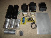
Nice! Is it choke, Output, and power transformer from L-R?
I'm contemplating breadboarding this as a stereo build once I sort out what power transformer in the parts bin is suitable.
I'm contemplating breadboarding this as a stereo build once I sort out what power transformer in the parts bin is suitable.
Choke, PT and then OPT.
Stereo certainly is possible if you have the iron to support it.
I am also starting to work on a seperate issue for the FET rails. In this build it will be schematic initially, however the common mode choke is worth playing with. I think it can be done for minimal cost and underhood space. When I get the parts to play with I will start a seoerate thread on that.
I was jealous to see you had already gotten yours until I got home and saw a box from Jack waiting for me.
These things are MASSIVE. Really massive! They make my ST-70 outputs look like little chokes.
These things are MASSIVE. Really massive! They make my ST-70 outputs look like little chokes.
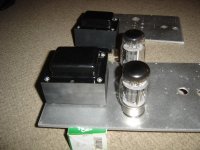
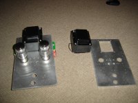
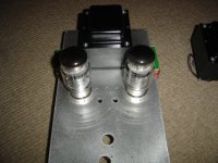
Tubemack, they are quite big and well made. Had to stop working on it tonight as the wife told me I needed to come up for air. But made progress. Have the two amp side top plates done. Will paint tomorrow and hopefully be transfering the components over by Wednesday.
I put some tubes in it for reference. Enjoy
I put some tubes in it for reference. Enjoy
Attachments
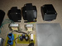
I am also quite envious of that iron. Wow...those are big suckers. They are at the top of my list of iron when I finally build that big AB2 amp...
OPT trannies or OT tubes? The OPT trannies are horizontal mounted. They have extra long bolts that fit through the holes at the four coners of the square cutout. The OT will sit on tube sockets that are mounted from underneath. When I get a little further later this week I'll take some close ups.
Did you get yours horizontal or vertical mounted. From what I can see it is just a different style bellend and longer bolts.
Did you get yours horizontal or vertical mounted. From what I can see it is just a different style bellend and longer bolts.
I missread, and confused your PT's and OPT's. My OPT's arrived as verticle models. Are you going with 4 chassis? Separate Power supplies?
Last edited:
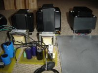
No. Two chassis. The power plate and amp plate will be mounted in a single frame. Smaller plates are easier to handle, dampen, and are mechanically decoupled. Not that I expect the PT or choke to buzz. With a center wooden rail it also gives me more mounting space underneath for things like C- filter and B1+ supply. I can also sheild if need be.
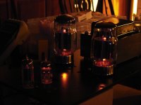
Let there be light!
No HV yet, but the filaments are lit. My filament transformer is too big and to get voltage down to acceptable range I had to put a 3.9R 25W in parallel as I didn't have low enough series resistor in my bin.
No HV yet, but the filaments are lit. My filament transformer is too big and to get voltage down to acceptable range I had to put a 3.9R 25W in parallel as I didn't have low enough series resistor in my bin.
Attachments
Need a Little Help on Bias
Power supply is up and running close to expectation. I don't have enough power resistor to simulate full load but it is close to voltage.
I do have a problem that I am struggling with. I cannot get the FET bias voltage to come off of the C- rail unless I almost connect it to ground. i.e 10k. Either I am missing something or the FET/CCS is bad. Both bias circuits are exhibiting the same thing. The FET gate is behaving as if it has a low impedance.
I don't have tubes in the circuit yet, but I should be able to set the kt88 bias regardless since it is just a voltage divider. C- rail is running -124V and B1+ is running +44V.
The one thing I am concerned about is that I am using a irfb20 however, my datasheet is for an irfb20PbF since it had the pin outs on it. my irfb20 datasheet doesn't. Pin 1 is Gate, Pin2 is Drain, Pin 3 is Source.
I attached the current schematic for reference. Am I missing something?
Attachments
Last edited:
Found it. Must of zapped the FET's at some point.
Voltage input and ltp up and running. If I get time tonight I will through some signal through the input and ltp.
The 12bh7 is running 100V anode with 8.7mA. Using a single green led with about 2.0V voltage. Total cathode bias is 2.2V.
LTP is running 8mA with 355V on the plate. There is about 15V difference between sides but I associate that with tolerence of the anode resistor.
Should they be matched?
There is about 15V difference between sides but I associate that with tolerence of the anode resistor. Should they be matched?
My guess is that the imbalance is due to the tube. If you have more, try another to see if the voltage changes. It has been my experience that perfectly balanced voltage does not always correlate with lowest overall distortion. If you think that it is due to the resistors, measure them, or swap them.
When building something like this, I fire it up in stages, and it looks like you are doing just that. I would make sure that you can get clean drive to the output tube grids (without output tubes) before ever installing the output tubes. That includes running some music through the amp and looking for "funny stuff". I do one channel at a time comparing the input to the grid signal with a dual trace scope. I have a storage scope which helps a lot.
Wish I had a storage scope. I wasn't too worried about the tubes being imbalanced. Per SY's thread a while ago tube imbalance isn't a problem, but I wasn't sure about the anode load. I will play with that tonight.
I will put some signal and start a few measurements tonight. I hope it stays together. So far it hasn't gone into oscilitory heaven.
I will put some signal and start a few measurements tonight. I hope it stays together. So far it hasn't gone into oscilitory heaven.
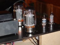
Its breathing
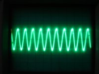
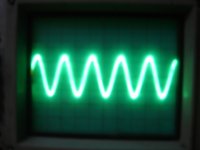
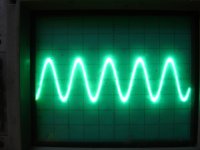
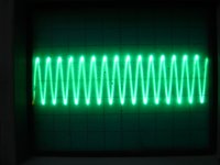
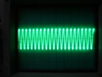
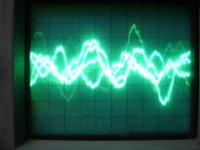
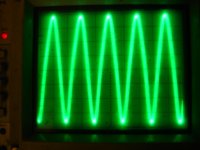
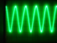
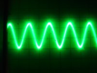
First few photo's of signal at the grid of the kt88.
100,1000,10000,20000,40000,music
Swing on scope is 75Vpeak input signal is 0.2Vrms. Will need a little feedback to keep it from being too sensitive but thats ok as it was designed for it. Will bias up the KT88's tonight and test them under load. Have some running to do first.
FYI The square wave isn't as good. WIll also play with that tonight
Attachments
It is playing music now. Tomorrow is a day for measuring and tweeking.
Way too early for impressions other than it has power.... Lots of it. I can clip the output tubes before I clip the driver.
It is very clear and dynamic. Drums are incredible campared to my SET. Curious to see the distortion spectrum... May have to look at that tonight.
B+ is still running about 490V. Plates are not glowing after an hour at 62mA bias.
Best of all no smoke! Just a couple of FETS that went silently in the night before.
I should mention that the above scope pictures were aat the onset of clipping of the driver stage.
First Measurements
Took some spectrum using 1kHz signal on a 8ohm resistive load.
First is at 100W, Second at 40W, and Third at 10W.
As you can see I have some filament hum at 60Hz. It is barely audible but present. I think alot of that is related to being on a breadboard.
It appears to have a nice spectrum. from 2nd order falling at each incremental harmonic
The square wave isn't as bad as I thought. My source isn't as good as I want so I will work on that tomorrow.
Attached are the spectrum and photo of trace for 100W, 40W, and 10W.
Attachments
- Status
- Not open for further replies.
- Home
- Amplifiers
- Tubes / Valves
- OPUS 5.0 A Modern Mullard