Cheers Jim
Cheers Jim. I'll have to get some carbon film resistors just for the digital lines.
Guido suggests inductance in the supply lines of the digital logic to reduce RF.
Should I use 1mH inductors and ferrites, or is this overkill?
(I am using VHC logic)
Cheers Jim. I'll have to get some carbon film resistors just for the digital lines.
Guido suggests inductance in the supply lines of the digital logic to reduce RF.
Should I use 1mH inductors and ferrites, or is this overkill?
(I am using VHC logic)
I'll check...
Okay I'll check.
I should be able to thread a ferrite bead on the inductor lead to increase the effectiveness of the RF filter. I'll put it on the IC side of business.
Does this sound reasonable?
Okay I'll check.
I should be able to thread a ferrite bead on the inductor lead to increase the effectiveness of the RF filter. I'll put it on the IC side of business.
Does this sound reasonable?
2 questions....
I just had a thought.... actually 2 questions....
1) Do I really nead inductors- don't the ferrites act as inductors?
(at 100Mhz the 100R impedance of a ferrite looks like the 100R impedance of a 0.16uH inductor- but is this enough?)
2) If I use resistors in the supply lines of my op-amps should I put ferrites on these too?
Re: Cheers Jim
May I suggest you consider carbon composition rather than film? Film would be mostly the same as any other film type. Carbon composition is the on which has "special" properties due to the "bulk" method of creating the resistance. I would guess this is what you need to use to achieve the desired effect.
Petter
Oli said:Cheers Jim. I'll have to get some carbon film resistors just for the digital lines.
May I suggest you consider carbon composition rather than film? Film would be mostly the same as any other film type. Carbon composition is the on which has "special" properties due to the "bulk" method of creating the resistance. I would guess this is what you need to use to achieve the desired effect.
Petter
My latest idea about digital supply decoupling.
Here is my latest idea about digital supply decoupling
- A 0.1uF ceramic capacitor provides localised decoupling.
- A ferrite bead reduces RFI in the supply line.
- OcCon electrolytic provides low frequency decoupling.
- The tendancy of ceramic capacitor and the OsCon to self-resonate is reduced by placing the ferrite bead between them.
See attached file...
Any comments?
Is this good practice?
Attachments

My idea for the analogue supply...
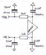
Here is my 'idea' for the analogue supply of my op-amp. Resistors dampen the tendancy of the ceramic capacitors to resonate with the OsCons.
Is this good practice?
Should I use ferrites in the supply lines too?
See attached file...
Here is my 'idea' for the analogue supply of my op-amp. Resistors dampen the tendancy of the ceramic capacitors to resonate with the OsCons.
Is this good practice?
Should I use ferrites in the supply lines too?
See attached file...
Attachments
Re: My idea for the analogue supply...
Oli said:Here is my 'idea' for the analogue supply of my op-amp. Resistors dampen the tendancy of the ceramic capacitors to resonate with the OsCons.
-------------------------------------------------------
Does this not increase PS impedance? Why need OSCONs for analogue PS, and why place Rs behind low esr cap. Just examine the PS to see if it rings or not!
Fair comment
Fair comment.
I could attempt to parallel the ceramic and the Os-Con first and see if it rings.
Again I would still use a ferrite in the digital supply to reduce noise induced in the supply lines by the logic.
and resistors in the supply line of the op-amp to reduce the frequency of circulating RF currents to within the power supply rejection limit of the op-amp.
Does this seem a better arrangement?
Any idea about ferrites in the op-amp supply?
Re: Fair comment
I could attempt to parallel the ceramic and the Os-Con first and see if it rings.
Again I would still use a ferrite in the digital supply to reduce noise induced in the supply lines by the logic.
and resistors in the supply line of the op-amp to reduce the frequency of circulating RF currents to within the power supply rejection limit of the op-amp.
Does this seem a better arrangement?
-----------------------------------------------------------------------
You could start from the simplest base. Use separate PSs, implememnt good practice on digital supplies. Buils lowest noise and lowest impedance analogue PS. Measure these with a wide band ac volt meter (10 uV full scale minimum,>1 MHz) and also look at the trace using avery wide band scope. You can easily be deceived by a 20 MHz scope!
😎
Just for reference
Oli,
May be you can find useful infos on this thread. A little bit hard to browse through, but quite informative. For ferrite an prefiltering, look at post #7, seems that a three leaded cap (NFM41 from Murata) does a nice job.
Happy bypassing 😉
Oli,
May be you can find useful infos on this thread. A little bit hard to browse through, but quite informative. For ferrite an prefiltering, look at post #7, seems that a three leaded cap (NFM41 from Murata) does a nice job.
Happy bypassing 😉
Re: My latest idea about digital supply decoupling.
Forget about good practices. Put the caps in the circuit and listen. I will not touch OsCons, as those were the worst sounding caps I tried. BG N type were much better in digital and analog decoupling. I'm using small values at the moment (4.7U) and even those sound much better than all the other caps I tested.
Oli said:
Any comments?
Is this good practice?
Forget about good practices. Put the caps in the circuit and listen. I will not touch OsCons, as those were the worst sounding caps I tried. BG N type were much better in digital and analog decoupling. I'm using small values at the moment (4.7U) and even those sound much better than all the other caps I tested.
BG N type were much better in digital and analog decoupling.
That is exactly my experience. But you have to dip them into snake oil three nights before the full moon.
Best regards,
Jaka Racman
Jaka Racman said:
That is exactly my experience. But you have to dip them into snake oil three nights before the full moon.
Best regards,
Jaka Racman
That is exactly a type of comment I would expect from a design engineer.
That is exactly a type of comment I would expect from a design engineer.
Seems you never actually listened to snake oil dipped caps.
Best regards,
Jaka Racman
Resistor inductance et al.
I have been doing some reading and thinking...
1) Regarding resistors in the digital signal line: Are 'low inductance' resistors needed?
We are already imposing slew rate limitations due to the resistor acting together with the input capacitance of the IC. Is the inductance significant?
2) Do I need to decouple digital ICs with Os-Con and ceramic capacitor in parallel?
Will the inductance of the tracks dominate such that the ceramic will be ineffective in practice and that the Os-Con will do 99% as good a job? I believe Guido Tent makes such a claim in his publication on 'decoupling digital ICs'.
Comments?
- Status
- Not open for further replies.
- Home
- Source & Line
- Digital Source
- Optimum Decoupling of Digital ICs