Then something's wrong somewhere because unless I've missed something (possible as I only had an hour of sleep last night) a characteristic of all symmetric Butterworth filters with the same corner frequency is a flat impedance.
The optimum number of components it the optimum number. No fewer. Components are a means to an end, they are not inherently evil.Consists of only four capacitors and four inductors. (no resistors).
Yes, I’m aware there are conflicting opinions on this. The fact that some crossovers can be optimised better than others doesn’t mean you need to blame and avoid circuits… much of the problem is actually acoustic in nature.

After altering several crossovers the impedance went from 7 ohms to 9 ish across the board and the sound quality is excellent.
No crossover only sounds great on quality full range speakers.
No crossover only sounds great on quality full range speakers.
mtidge
I am not dismissing the VituixCAD. i like it. Yes, the vector sum of the voltages is the SPL.
However, In the real world, the SPL curve only applies to someone sitting directly in front of the loudspeaker, at zero degrees azimuth. If the SPL is flat for him, it will have a dip somewhere else sitting at a different angle.
Because the voltages in a crossover typically meet at the -6dB point, there will be a 3dB drop in power at that frequency. If in the room, the three pressure waves from the three drivers become incoherent there will be a 3dB dip in SPL.
Because the polar patterns of different diameter drivers are not the same, their pressure waves can never be coherent. Thus the SPL calculations of a computer are fairly worthless in the real world.
Sorry, your crossover is worthless in the real world of loudspeakers.I have developed what I believe is an exceptional audio crossover.
Member @Shaun gave good explanation why:
You have made what is commonly referred to as a textbook crossover. Kudos for your progress thus far. There are four factors that will impact the usefulness your filter: driver impedance (this you have identified), driver sensitivity, in-situ driver frequency response and driver useable bandwidth (distortion profile and directivity).
The problem with textbook crossovers is that it assumes that all the extra factors mentioned above are ideal. Dedicated loudspeaker design softwares typically have utilities that account for all the above-mentioned parameters and enable the user to assess the final product.
Have you ever tried to design crossover with VituixCAD (or something similar)? Operantly not, according to what you wrote:
My advice: buy a measuring equipment (it is not expensive) and learn how to use the free VituixCAD (or other crossover simulation software) - you will be surprised how software calculation will be similar (identical!) to the real world measurements.Thus the SPL calculations of a computer are fairly worthless in the real world.
I'm just linking in my earlier post about "book" cross-overs.
They can work to an extent if you use lots of extra bits like Zobels, resonance peak filters and such and if near enough is good enough
https://www.diyaudio.com/community/threads/modifying-prebuilt-book-crossovers.414326/#post-7728797
They can work to an extent if you use lots of extra bits like Zobels, resonance peak filters and such and if near enough is good enough
https://www.diyaudio.com/community/threads/modifying-prebuilt-book-crossovers.414326/#post-7728797
I'm afraid you are lagging far behind the level of technology commonly available to humble DIYers for free. We are no longer limited to on-axis measurement and design.mtidge
I am not dismissing the VituixCAD. i like it. Yes, the vector sum of the voltages is the SPL.
However, In the real world, the SPL curve only applies to someone sitting directly in front of the loudspeaker, at zero degrees azimuth. If the SPL is flat for him, it will have a dip somewhere else sitting at a different angle.
Because the voltages in a crossover typically meet at the -6dB point, there will be a 3dB drop in power at that frequency. If in the room, the three pressure waves from the three drivers become incoherent there will be a 3dB dip in SPL.
Because the polar patterns of different diameter drivers are not the same, their pressure waves can never be coherent. Thus the SPL calculations of a computer are fairly worthless in the real world.
Here is some reading material. This stuff you can do at home.
https://www.sausalitoaudio.com/wp-content/uploads/2018/07/Interpreting-Spinorama-Charts.pdf
AllenB
Thank you for allowing me to comment on this forum.
You and others have said that adding components could result in a better crossover.
The design objective for this crossover was to have a constant power output. (20 Hz to 20 kHz) . With this crossover. one can apply 2.83 Volts at any frequency and the total output power will be 1.0 Watts
(For theoretical crossovers, we need to stick with 8 Ohm ideal resistor loads)
Here is a challenge to anyone. Design a 2nd order, 3-Way crossover, with any number of components, that has a flatter output power response. 🙂
Well, that would be a mite difficult, since a well-known and unremarkable fact about Butterworth filters (the textbook symmetric 2nd order values you've plagiarised and are trying to claim copyright for) is the fact that electrically speaking they have a flat power response.
This is all rather irrelevant (apart from the plagiarism bit) as far as loudspeakers are concerned though, since like all textbook electrical filters assuming static resistive loads, it takes zero account for the varying frequency, phase and impedance loads of actual, non-coincident drive units. In that context, it's more than a bit ironic that you try to claiming modelling software is unable to account for off-axis responses. Actually, good examples do if you provide the data. In fact, even more limited varieties can -some may only be able to display one axis at a time, but display them they will, when supplied. Garbage in, garbage out: it was ever thus. Much like this 'optimum crossover' in fact, which as Self pithily describes it '...[a] classic bit of crossover misdesign that has been published in circuit ideas columns and the like a thousand times...' (Self, D. The Design of Active Crossovers [London: Focal, 2011] p.62) to which I'd probably add 'only a thousand'? 😉
This is all rather irrelevant (apart from the plagiarism bit) as far as loudspeakers are concerned though, since like all textbook electrical filters assuming static resistive loads, it takes zero account for the varying frequency, phase and impedance loads of actual, non-coincident drive units. In that context, it's more than a bit ironic that you try to claiming modelling software is unable to account for off-axis responses. Actually, good examples do if you provide the data. In fact, even more limited varieties can -some may only be able to display one axis at a time, but display them they will, when supplied. Garbage in, garbage out: it was ever thus. Much like this 'optimum crossover' in fact, which as Self pithily describes it '...[a] classic bit of crossover misdesign that has been published in circuit ideas columns and the like a thousand times...' (Self, D. The Design of Active Crossovers [London: Focal, 2011] p.62) to which I'd probably add 'only a thousand'? 😉
Last edited:
Nicely put!the textbook symmetric 2nd order values you've plagiarised and are trying to claim copyright for
Just calling it as I see it. 😉 If any of my students had tried that, it would be an automatic fail & would also have to be elevated to faculty level. We're informal here of course, so nobody's expecting academic referencing (!) but when you take prior art, fail to mention the fact, and then try to claim copyright (however meritless) for it, that's a bit more of an issue. 
How did you obtain Copyright on public domain stuff? Can you provide proof of Copyright 2024?Optimum Crossover
I have developed what I believe is an exceptional audio crossover. I have tested it theoretically using the circuit analysis program Nova-686. The frequency response is perfectly flat from 20 to 20 kHz.
I am inclined to believe that this may be the best possible passive, three-way crossover. However, I am open to feedback and would appreciate it if someone could review it and provide his opinion.
Crossover Characteristics
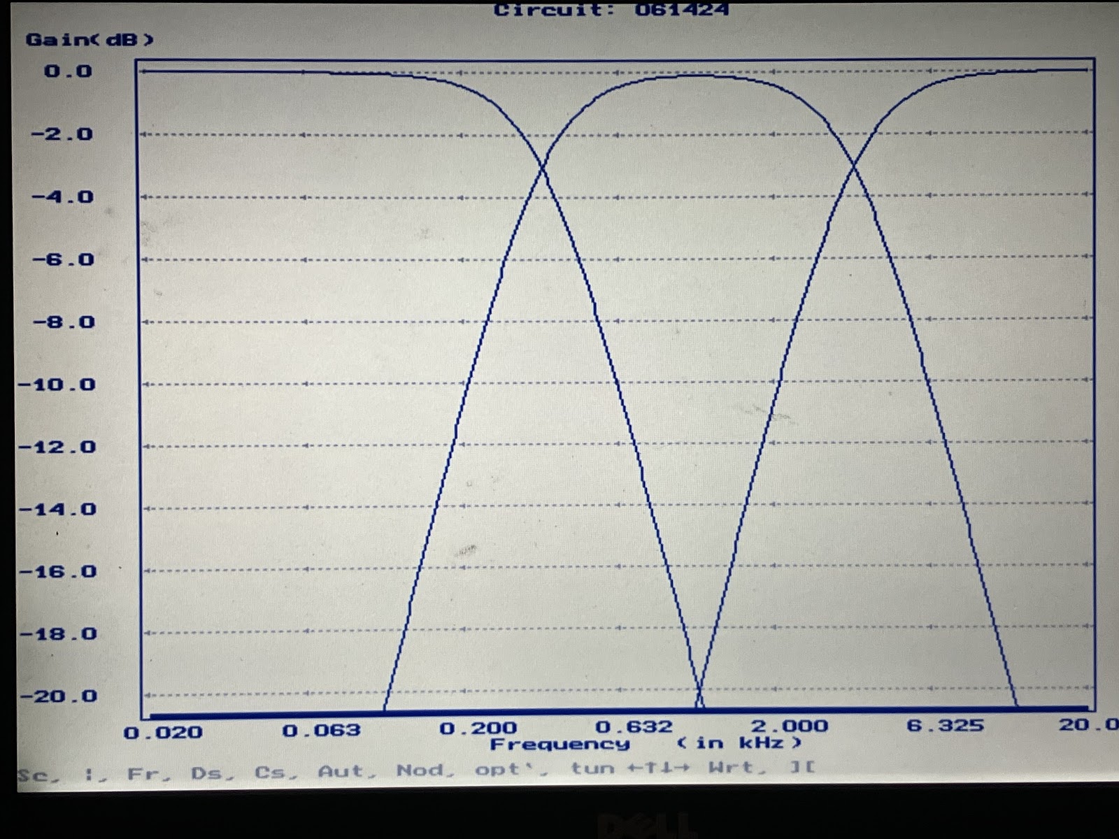
- Flat frequency response. +/- 0.01 dB, 20 Hz to 20 kHz.
- The input impedance is a constant at 8 Ohms
- Good square wave response..
- Group delay, 670 usec max.
- Consists of only four capacitors and four inductors. (no resistors).
Crossover Frequencies
The frequencies chosen serve as a good starting point for the DIY builder.
20 Hz to 350 Hz.
350 Hz to 3500 Hz
3500 Hz to 20 kHz
Physical Limitations
Moving from the theoretical to the practical presents some challenges.
Audio drivers do not exhibit ideal impedances. This leads to non-flat frequency responses. However, Zobel networks can be employed to address this discrepancy.
It is difficult to go from a theoretical design to one using standard parts. However, this design achieves optimum performance using standard part values.
Schematic “Best Possible Passive Crossover”
(3-way 2nd order)
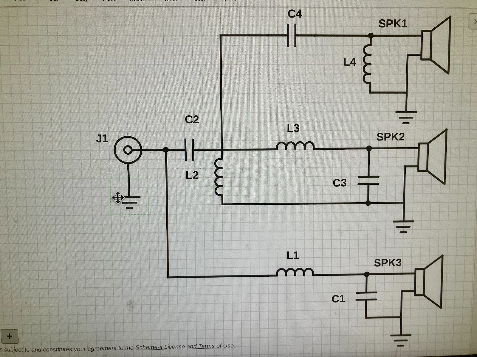
PS (The mid driver must be phase inverted.)
L1 = 5.0 mH C1 = 39 uF
L2 = 5.0 mH C2 = 39 uF
L3 = 0.5 mH C3 = 3.9 uF
L4 = 0.5 mH C4 = 3.9 uF
Frequency Response
Copyright 2024
Robert Stanton
I have read your thread and I do not know how to calculate the output power.The design objective for this crossover was to have a constant power output.
This may be true in an analog electrical circuit, although I can think of situations where it would not be. But once the electrical power is radiated out of the speaker as acoustical energy, a flat power response is highly unlikely to achieve the goal of a "flat audio system". The radiation pattern of a 3-way speaker is complex, and each driver has its own frequency-dependent radiation pattern. The cabinet/baffle that the drivers are mounted on will also have a dominating effect on the radiation pattern.In my opinion, a flat audio system is characterized by a consistent power output measured in Watts, across the frequency range of 20 Hz to 20 kHz.
Many research papers and books have been written on this subject.
As Shaun eloquently stated, there is no "ideal" crossover, put drivers in a box and the frequency response goes to hell, a crossover should be designed based on the needs of the system, specs of the drivers and in box measurements, it's a huge challenge to create a coherent system without actual in box measurements and an optimizer.
there is no "ideal" crossover
No crossover? But that brings other compromises. Still a segment of out hobby that is growing by leaps & bounds.
dave
Here's the simulation (model) (from here https://www.audiosciencereview.com/...ers-h-v-off-axis-measurements-included.41757/)

And here is the measurement (https://www.audiosciencereview.com/...chano23-open-source-diy-speaker-review.54066/)

To me - when measurement matches the model this well - it says the tools (VituixCad) and process that made them are good and trustworthy.
And here is the measurement (https://www.audiosciencereview.com/...chano23-open-source-diy-speaker-review.54066/)
To me - when measurement matches the model this well - it says the tools (VituixCad) and process that made them are good and trustworthy.
Question: can the software model "LX" configuration with up-firing midbass? Or "omni"? Thanks.
I've made a whole bunch of them and posted to the fullrange forum photo gallery because many are "fullrange" drivers crossover-less or minimalist passive. Some OB frontal some not. Last night:
https://www.diyaudio.com/community/threads/full-range-speaker-photo-gallery.65061/post-7736554
The Eazies worked very well (no surprise there) but Textreme MW19TX-8 as OB fullrange over 10" Pearl River (27L closed can), details sounded "rounded-off" at all frequencies. I didn't have time last night to mount the Satori TW29R-4 (series first-order from before). Even though the Textreme tone-swept like a fullrange it didn't work like one.
You can hold vituixcad's hand to model this. You would need to do it in stages to assess the different radiation levels (from direct to reverberant) and you will have to make your own judgement on what they mean. You would need to visualise how it comes together before you decide how to get vituixcad to help.can the software model "LX" configuration with up-firing midbass?
This is the Multi-Way sub-forum. No crossover implies single driver, full range. There's a whole other sub-forum for that.No crossover? But that brings other compromises. Still a segment of out hobby that is growing by leaps & bounds.
dave
- Home
- Loudspeakers
- Multi-Way
- Optimum Crossover