AllenB
Scottmoose
One of the funniest comedic techniques is to have two people arguing while discussing entirely different topics. A classic example is the famous Abbott and Costello skit about "Who's on First?" I'm discussing an electrical crossover and its characteristics, while you're talking about acoustical power.
Mr. Scottmoose keeps claiming that it's easy to create a Butterworth filter with constant impedance, but he hasn't provided an example to demonstrate this.

Er -a well-known and unremarkable trait of Butterworth filters with symmetrical corner frequencies is the fact that they sum to a flat impedance. I don't need to prove a thing: you're the one who is not only claiming something contrary to very basic electrical filter design, but also trying to pass off those self-same standard 2nd order electrical Butterworth filters as something different (while also claiming copyright).
For the benefit of any poor souls reading this and buying into the OP's twaddle however: FR (both polarities) and impedance of electrical 1st, 2nd, 3rd & 4th order Butterworth filters with a 1KHz corner into a resistive 8ohm load. Yes -astonishing revelation: a symmetric Butterworth filter electrically speaking sums to a flat impedance (and FR, whichever polarity). Be still my heart. 🙄
I eagerly look forward to seeing which way the OP will now try to claim these are somehow 'invalid'. It'll be interesting, no doubt. 🤣
Attachments
-
 1st orderFR.gif21.6 KB · Views: 38
 -
 B4impedance.gif14.3 KB · Views: 43
 -
 B4inversepolarityFR.gif23.7 KB · Views: 38
 -
 B4samepolarityFR.gif22.9 KB · Views: 34
 -
 B3impedance.gif14.3 KB · Views: 35
 -
 B3inversepolarityFR.gif22.8 KB · Views: 37
 -
 B3samepolarityFR.gif22.8 KB · Views: 37
 -
 B2impedance.gif14.3 KB · Views: 36
 -
 B2reversepolarityFR.gif22.7 KB · Views: 35
 -
 B2samepolarityFR.gif23.8 KB · Views: 42
 -
 1storderimpedance.gif14.3 KB · Views: 42
 -
 1storderinversepolarityFR.gif21.6 KB · Views: 39
Just to underline the point here:
In post 01, the OP states symmetrical corner frequencies of 350Hz and 3.5KHz. He doesn't specify the impedance other than it is static resistive, and it doesn't exactly take much working out that it's a nominal 8ohm. The filter values for this 'copyrighted', very definitely not basic, symmetric 2nd order electrical Butterworth filter values provided are:
L1 = 5.0 mH C1 = 39 uF
L2 = 5.0 mH C2 = 39 uF
L3 = 0.5 mH C3 = 3.9 uF
L4 = 0.5 mH C4 = 3.9 uF
Now, I wonder what the 2nd order Butterworth values for those might be, into a static 8ohm resistive load?
LP: 5.14mH, 40.19uF. Or, rounded to nearest commonly available standard component values, 5.0mH & 39uF.
BP: 40.19uF, 5.14mH & 0.51mH, 4.02uF. Or, rounded to nearest commonly available standard component values, 39uF, 5.0mH & 0.5mH, 3.9uF.
HP: 4.02uF & 0.51mH. aka 3.9uF and 0.5mH.
Attachments
Last edited:
Is it possible that the OP's posts are (wholly or largely) AI generated, and this is all a bad joke?
Human troll, I would guess, unless AI has started on that game, in which case we're in for a merry time. 😉
One minor edit re 63 above (lest the OP attempt to use it as a deflection): when I wrote 'and FR, whatever polarity' it is in reference to odd, not even order Butterworth filters. The time for editing expired before I could tweak that part, although if a mod could, well & good.
One minor edit re 63 above (lest the OP attempt to use it as a deflection): when I wrote 'and FR, whatever polarity' it is in reference to odd, not even order Butterworth filters. The time for editing expired before I could tweak that part, although if a mod could, well & good.
Adason
I don’t think you fully understand how copyrights work. I create an original circuit and then copyright it. If you dispute my copyright, all you need to do is demonstrate that this circuit existed prior to my copyright date.
I don’t think you fully understand how copyrights work. I create an original circuit and then copyright it. If you dispute my copyright, all you need to do is demonstrate that this circuit existed prior to my copyright date.
So you think a symmetrical 2nd order 3 way filter topology using standard Butterworth values is ‘original’. That’s a novel argument. I don’t think anybody’s tried that one before 😂🤣
Original circuit?! ORIGINAL?!?!?! Are you serious?!?!?! Try to read some basic books for beginners...I create an original circuit and then copyright it.
And you copyrighted it?! You are hilarious!
Here is the crossover from HSR140 loudspeaker which was popular in my country 50 years ago!!! 50 years ago!!!
Enjoy:
Your cruelty to animals (beating a dead horse) is unheard of!
Here is your "original" crossover (from post #1):
Optimum Crossover
I have developed what I believe is an exceptional audio crossover.
Schematic “Best Possible Passive Crossover”
(3-way 2nd order)
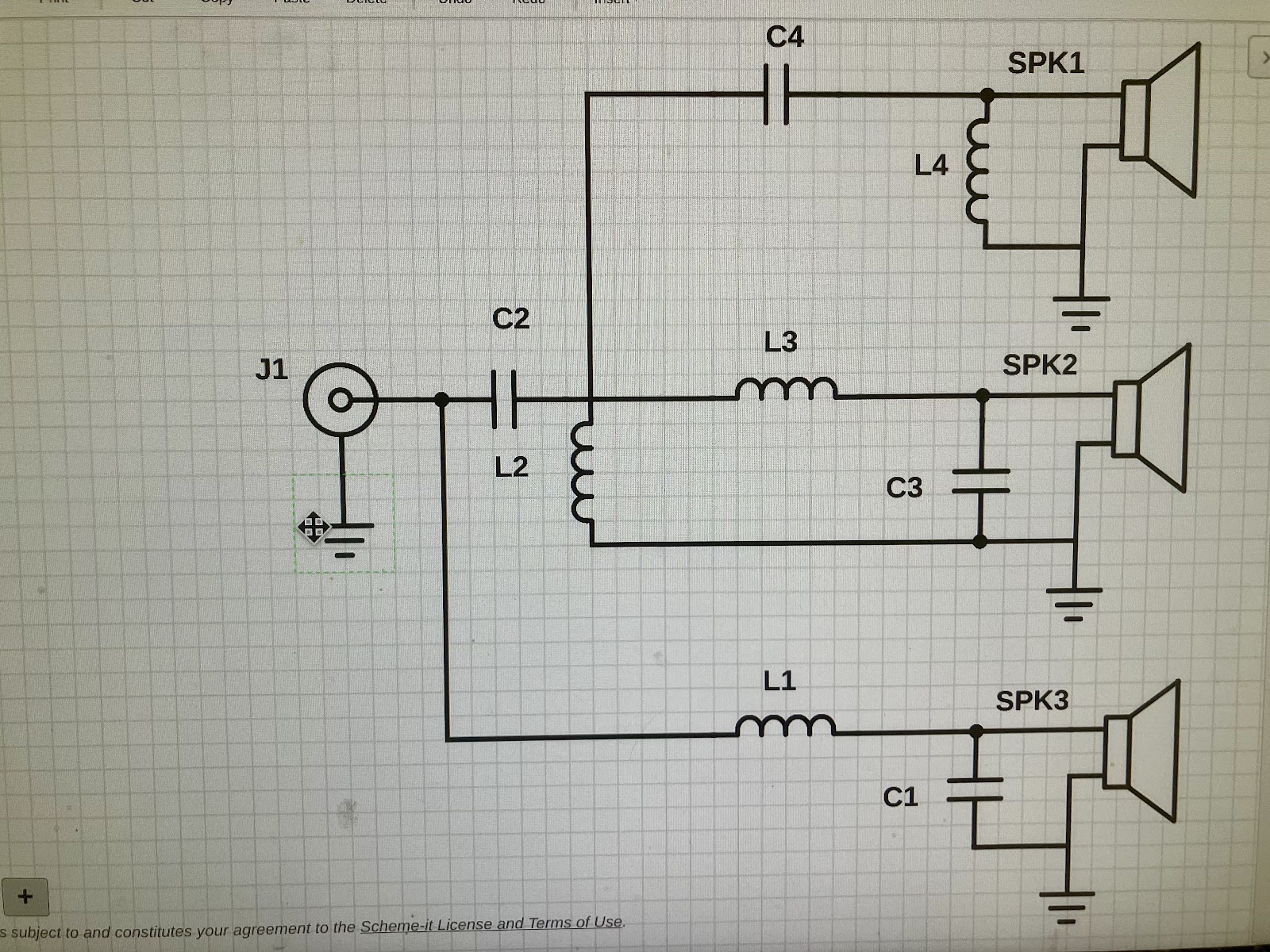
Copyright 2024
Robert Stanton
You copyrighted crossover 50 years old?! 🤣🤣🤣
Scottmoose
I noticed the adjustments you made to the crossover's component values to align them more closely with theoretical expectations. The changes are quite minor, and the most effective way to observe their impact on impedance is to analyze the S parameters of the crossover. I conducted a sweep of S11 and S21 from -20 Hz to 20 kHz. The worst return loss recorded was 51 dB at 3600 kHz. After that, I replaced the components with your suggested values and performed another S11 sweep. The return loss at 3600 kHz dropped to 45 dB. This indicates that the impedance shifted from 8.019 -j 0.39 with my values to 7.930 -j 0.56 with your suggested values. This crossover is already optimized, and any further modifications are likely to degrade its performance.
I noticed the adjustments you made to the crossover's component values to align them more closely with theoretical expectations. The changes are quite minor, and the most effective way to observe their impact on impedance is to analyze the S parameters of the crossover. I conducted a sweep of S11 and S21 from -20 Hz to 20 kHz. The worst return loss recorded was 51 dB at 3600 kHz. After that, I replaced the components with your suggested values and performed another S11 sweep. The return loss at 3600 kHz dropped to 45 dB. This indicates that the impedance shifted from 8.019 -j 0.39 with my values to 7.930 -j 0.56 with your suggested values. This crossover is already optimized, and any further modifications are likely to degrade its performance.
I addressed electrical matters and said I didn't find them particularly relevant/interesting to the topic directly at hand.AllenB
Scottmoose
One of the funniest comedic techniques is to have two people arguing while discussing entirely different topics. A classic example is the famous Abbott and Costello skit about "Who's on First?" I'm discussing an electrical crossover and its characteristics, while you're talking about acoustical power.
If you don't believe this is correct, would you care to show how?
I knew what you meant.. it's shown clearly in the simulations. Thanks for the clarification.One minor edit re 63 above (lest the OP attempt to use it as a deflection): when I wrote 'and FR, whatever polarity' it is in reference to odd, not even order Butterworth filters. The time for editing expired before I could tweak that part, although if a mod could, well & good.
You made the small mistake (I assume) of moving the woofer and midrange voicecoil towards the mic / listener.Just for fun I put your design into VituixCAD and your filter is what you describe, however even with perfect 8 ohm concentric drivers the response isn't close to what you described.
View attachment 1325963
View attachment 1325964
View attachment 1325968
positive Z is further away in VCad.
Sonce
The book of Ecclesiastes 1:9,
"What has been will be again, what has been done will be done again; there is nothing new under the sun."
There goes my copyright. ha ha ha ha.
Thank you all for your comments.
The book of Ecclesiastes 1:9,
"What has been will be again, what has been done will be done again; there is nothing new under the sun."
There goes my copyright. ha ha ha ha.
Thank you all for your comments.
Your copyright is invalid, because that crossover topology is known at least 50 years (see my post above). So you can put your copyright where sun never shines... in a dust bin, of course.there is nothing new under the sun."
There goes my copyright.
Maybe I misunderstood you - English is not my native language (obvious, by so many grammar mistakes I am making), so maybe I am not expressing myself in a correct way and maybe I am not recognizing that some of my explanations may be similar to some idioms - which true meaning I don't know.
Last edited:
Pardon? No changes at this end. As I illustrated, you (nobody else) simply posted 2nd order electrical Butterworth values for the stated frequency & a static 8ohm impedance figure, rounded to the nearest widely available standard component values. Ever since, you have spent multiple posts desperately trying to evade or deflect from that fact (such as with this latest twaddle -the classic, and transparent attempt at inversion beloved of the internet troll), while trying to claim 'copyright' for a perfectly ordinary 3-way topology that's been used countless times since the 1960s (and can be found in most any textbook on basic filter design), and claiming symmetric Butterworth filters do not sum to a flat impedance, despite this being a standard characteristic known since Stephen Butterworth invented them in the late 1920s (published 1930).Scottmoose
I noticed the adjustments you made to the crossover's component values to align them more closely with theoretical expectations. The changes are quite minor, and the most effective way to observe their impact on impedance is to analyze the S parameters of the crossover. I conducted a sweep of S11 and S21 from -20 Hz to 20 kHz. The worst return loss recorded was 51 dB at 3600 kHz. After that, I replaced the components with your suggested values and performed another S11 sweep. The return loss at 3600 kHz dropped to 45 dB. This indicates that the impedance shifted from 8.019 -j 0.39 with my values to 7.930 -j 0.56 with your suggested values. This crossover is already optimized, and any further modifications are likely to degrade its performance.
Last edited:
Yes, well we're all wiser now for it. There was never really any concern, nothing gets past the fine members of this forum.
- Home
- Loudspeakers
- Multi-Way
- Optimum Crossover