Hi TomHi Hans
Been playing with the two high torque hurst motors I have while waiting for my parts. These noisy monsters on in sperate 6" pods with lead all over the place. I wondered how much noise was getting to cart so tried your cart on the record no belt trick. Holy crap not a pretty sound!!!
I decided to get rid of this transfer of noise so I used some 29 cent rubber/cork/rubber pads and Baltic birch plywood. I isolated the motor pod/turntable/tonearm problem solved. Using the cartridge and amps for noise detection is a great idea.
When I was playing around I hooked up a fluke a/c meter to the amp speaker terminals. When the refrigerator kicked on the reading on the meter when up a lot. So I pulled the cart up meter when back to normal reading. So with the cart on the record it was picking up vibration from a refrigerator 20 ft away thru the wood floor up a rack with at least 500 lbs of stuff lead loaded MDF brass cones aluminium/wood plinif 32 lb lead loaded platter 1/4 PVC mat. So much for mass taking care of the problem. 29 cent rubber cork pads who would of thought??
Can not wait to get the parts to build the controller. Will let you guys know how it turns out.
Enjoy the ride
Tom
I went the same twisty road as you just did.
Wooden floor, heavy granite table, but nevertheless noise transfer through the floor to the Cart. Even simple knocking on the floor could be heard.
That's why I places a Ginko Isolation Platform between granite table and Pick-Up, which solved the problem completely.
See here for more info:
Review: Gingko Isolation Products, Cloud 10, Cloud 11, Mini Clouds
Hans
Guys, maybe you got experience with Hurst 3001-001 motors... I got brand new directly from Hurst and connected it exactly as they advised with new Hurst Cap. I see it heats up to 45-50 Deg C after 30-40 min of idle run and stay that hot. No load yet...
Is it normal for AC direct drive motors? Can't test old one (exact same model from 80s) since it is dead.
BTW, waiting for parts to arrive for your Sine generator. Probably next week...
Please advice if you know.
Thank you.
Alex
Sent from my iPhone using Tapatalk
Is it normal for AC direct drive motors? Can't test old one (exact same model from 80s) since it is dead.
BTW, waiting for parts to arrive for your Sine generator. Probably next week...
Please advice if you know.
Thank you.
Alex
Sent from my iPhone using Tapatalk
Hey Ralph
Got the amps Friday and the rest of the stuff we be here this week. Looking over your pictures and schematic was trying to figure out how you hooked up the input. The only information I could find on the web about these amps was on there web site.
It seems like you have to run the signal to both the + and - terminal and gnd to gnd. I am guessing you bridged it at the board. The divider and low pass filter you show in your schematic looks like you can take the voltage from two spots and is this a 4 order low pass filter.(2 caps 2 resistors per input channel).
From the looks of the last picture you are not feeding the signal thru the 1st resistor but it is hard to see from the pictures. If you could do a hook up schematic on how you did it, it would be great.
I sent you a email with the machine shop stuff but could not get the pictures to go thru.
Thanks Tom
Hi Tom,
Sorry about the picture, it was taken between the 12 and 24V setups.
To setup the amps for single ended inputs simply short out the -ve and gnd connections ( I just bent the pins together and added solder).
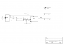
Hopefully the diagram attached will cover most of the questions; I'm using it for 3 phase with my Papst delta wound motor, but it could just as easily be used as a 2 phase setup (with the correct transformers) or even as a single phase generator where the incoming mains is dirty, or where a variable frequency supply would allow a turntable designed for US to be used in Europe.
Ralph
Sorry about the picture, it was taken between the 12 and 24V setups.
To setup the amps for single ended inputs simply short out the -ve and gnd connections ( I just bent the pins together and added solder).
Hopefully the diagram attached will cover most of the questions; I'm using it for 3 phase with my Papst delta wound motor, but it could just as easily be used as a 2 phase setup (with the correct transformers) or even as a single phase generator where the incoming mains is dirty, or where a variable frequency supply would allow a turntable designed for US to be used in Europe.
Ralph
Attachments
Hi Ralph
They a picture is worth a 1,000 words but in this case it is a schematic. Nice software!!! Got lucky the Chinese stuff got here quick.
VPI just came out with controller with no feedback or phase control. Their whole marketing thing is based on all analogue no digital. Well as much as I am am a tube/transformer kind of guy I wonder what does a motor really want to see. Well first things first. Can throw a linear power supply in down the road.
Thanks so much for the information. This thread is got to be a great tool for anyone looking to build a controller which does not seem to be available in the market place.
Tom
Hi Tom,
I do feel a little guilty of hijacking this thread somewhat; do you think its worthwhile asking the moderators if its worth spinning it off into a separate more general AC controller thread?
I do feel a little guilty of hijacking this thread somewhat; do you think its worthwhile asking the moderators if its worth spinning it off into a separate more general AC controller thread?
Hi Ralph
Maybe Hans will chime in here. Both you and Hans have been most valuable in this thread. Bill from Phoenix has also thrown in some great information. From my stand point we have stayed on topic ( controller that splits phases) Han did a 2 phase which has been going for years and yourself 3 phase with affordable parts.
I think the more DIYers we have who build and share their results the better. You could start another thread on step by step on how you built it and potential mods in the future kind of thing. Again I am grateful for all the real information that has been presented here. Hans started it so I hope he shares his thoughts on this.
Thanks Tom
Hi Tom,Hi Ralph
Maybe Hans will chime in here. Both you and Hans have been most valuable in this thread. Bill from Phoenix has also thrown in some great information. From my stand point we have stayed on topic ( controller that splits phases) Han did a 2 phase which has been going for years and yourself 3 phase with affordable parts.
I think the more DIYers we have who build and share their results the better. You could start another thread on step by step on how you built it and potential mods in the future kind of thing. Again I am grateful for all the real information that has been presented here. Hans started it so I hope he shares his thoughts on this.
Thanks Tom
Starting this thread was just to make people aware that (expensive) commercial products are not always giving the user the best possible solution.
So in whatever direction the ball goes, as far as positive ideas are being developed, I will support it.
Hans
P.S. A small comment on Ralphs circuit diagram: The used 0.33uF capacitors will usually have a tolerance of 20%.
This will substantially affect the careful adjusted phase angle between the phases. A much smaller capacity would be better, under the assumption that sample frequency by which the frequency is generated is much higher.
Hi Hans,
I'm sorry,I should have mentioned this.
I was lucky enough to have a selection of Polyester caps to hand, which I matched to better than 2%.
If you match the caps as closely as possible; and also use low tolerance resistors, 1 or 2%, then the variation in phase shift should be small.
If you reduce the capacitors to 0.033u, even with 20% components any variation of phase shift between sections should be small enough to be ignored (1~3 deg.).
One easy way of measuring this is to use one of the signal generator outputs and feed it to all three low pass sections in parallel. Measure the voltages between the outputs of the LP filters . Assuming the resistors are well matched the difference between the outputs should drop close to 0 when the capacitors match.
Hi Guys
Got everything but the power supply so going to start building today. Going to hook up the Hurst motors to the 2 phase first. So using the eBay generator is phase 1 at 0 and phase 2 at 90. On the Hurst motors they tie the 2 blue wires together and put a cap between the black and red. Then you feed wall ac to blue and red. How would hook up the Hurst to new controller to get the phases correct?
On a theory note. Are the motor always on a perfect 90 degrees on the phases. For example could a 0 / 89 degree off set make a certain motor run smoother. You can vary the degrees by 1 on this generator.
Thanks Tom
The 3 phase generator I referenced in an early post is adjustable for phase, voltage and frequency.What about controlling speed with this setup?
If the motor is synchronous then frequency is all you need to adjust, if it's not synchronous then the frequency is the primary control, voltage a minor secondary adjustment.
HI Tom, glad you've got all the bits now. As far as the connections are concerned separate the blue wires and find which ones make a circuit. Connect 1 pair to one transformer output and the other pair to the second. If the motor runs the wrong way reverse the connections of 1 winding.
Good luck
Ralph.
Good luck
Ralph.
How about my previous suggestion of looking through the catalogs for a lower voltage ac motor? There might be a better one one out there, now that we can control voltage and frequency.
I have a Pro-Ject motor 2 phase, runs on 16v 2VA. They're only $50, but may not be that good? I was thinking I could feed a class D amp with a sine generator and skip transformers etc. I may put voltage displays and pots between the motor and output channels in order to fine tune output.
I have a Pro-Ject motor 2 phase, runs on 16v 2VA. They're only $50, but may not be that good? I was thinking I could feed a class D amp with a sine generator and skip transformers etc. I may put voltage displays and pots between the motor and output channels in order to fine tune output.
Does your motor have 3 or 4 wires, and is the second phase generated by means of a capacitor connected to the motor drive signal.
If so, there is no technical difference with the other 2 phase motors in this thread.
When using amps that can deliver the 16 Volt with enough power, you can drive the motor directly without transformers.
Hans
My VPI Classic turntable is with a Hurst PB motor, but its adapted for my region for 220-240VAC/50hz. The motor is 230V/50hz/500rpm/0.25uF capacitor type model.
The pulley is made for 500 rpm. Since owning it but never checked the actual circuit, I did a check very recently for the first time and may have found something quite unusual in the circuitry. Its wired with a 3k/10W resistor in series with 2 X 0.22uF polypropylene caps in series (total 0.11uF) for phase shift. I find this a bit unusual as most table motors (especially those using Premotec) I've seen adapted for 220-240VAC/50hz are commonly using 0.22uf cap. I've not seen any with caps below 0.2uf being implemented.
I wrote to VPI and there's been no reply, maybe its ignored, I should presume the circuit is spot on correct and not to be disturbed. What do you think?
So do you worry about the resistor, or the value of the cap?My VPI Classic turntable is with a Hurst PB motor, but its adapted for my region for 220-240VAC/50hz. The motor is 230V/50hz/500rpm/0.25uF capacitor type model.
The pulley is made for 500 rpm. Since owning it but never checked the actual circuit, I did a check very recently for the first time and may have found something quite unusual in the circuitry. Its wired with a 3k/10W resistor in series with 2 X 0.22uF polypropylene caps in series (total 0.11uF) for phase shift. I find this a bit unusual as most table motors (especially those using Premotec) I've seen adapted for 220-240VAC/50hz are commonly using 0.22uf cap. I've not seen any with caps below 0.2uf being implemented.
I wrote to VPI and there's been no reply, maybe its ignored, I should presume the circuit is spot on correct and not to be disturbed. What do you think?
Hans
- Home
- Source & Line
- Analogue Source
- Optimally driving a (VPI) synchronous turntable motor