Nigel, I spent about 35 years as a "color stripper" (old term) or image assembly (new term), spending 8 hours a day or more, staring at a light table with layers of negatives, always mirror image, and sometimes upside down. I noticed that towards the end of my career I had trouble distinguishing whether something was a mirror image or not. I usually don't have too much trouble wiring even pretty complex circuits. However I completely fowled this one up. I'll learn to label things better in the future. I could see that being dyslectic can give unique understanding, however in this case it didn't work out too well. Nothing I can't handle, I'll just have to be more careful in the future. I got too cocky about my ability to do mental gymnastics. I drew no paper guide nor labeled anything, just had a picture in my head, some of which was swapped.
I was talking about you with my lady friend last night. She knew of the experiments to change vision the correct way up that caused people to correct in their minds. I said to Colleen I can read upside down and back to front. She whilst taking the p--s was interested. I have great respect for the work you did, I suspect there is a University out there who would love to test you before the effect reverses.
I only realised in recent years my ability to see complete engines etc working in my mind is rare. I suspect I just swapped the words for pictures. My dad says he can read words in his head. I can't.
I made a small error yesterday. The shed was cold and bearing drag was hiding the better transformer ratio. It is about 15% better. This means a 50VA transformer is as lossy as the data states and beat the 100 VA of less ideal ratio.
The Garrard 601 is unusual in needing 160V rms and 70Hz +/- 15 % is possible. Also 52 Hz +/- 6%. The 78 rides on the 45 speed as draw up pully of 10.4 mm which is also an oil deflector. 33 1/3 is direct to the 6 mm shaft. One thing I will do is wind the FET soft start DC supply by hand on the output toroid. I suspect 2 metres of standard thin insulated wire on the torioid will work. This will ensure any gate ripple is of the same frequency as the supply and is hyper low cost as a bonus. It also saves box space. 10 minutes work at worse.
The FET losses are now down to 300 mV each on the un-ideal IRF640. If I use very common IFR540/30 I should be where I want to be. I have a hunch 0R2 would be a nice helpful loss. The two transformers I am using are marginally too small and too big on ratios. The ideal one is off the shelf. That's good. Tiger of Peterborough UK make excellent bespoke ones at very good prices if needed. I shall use Vigortronics as they are not bad. The purity of the sine wave is first class and that's before doing the technical stuff.
Although I doubt it will interest people some sine waves are very high distortion yet look OK on the scope. Some are lower THD and look worse. This is because we say THD with no harmonic weighting. If the distortion is typical SE triode valve type of perhaps 3% it will sound OK musically. It will also drive a motor quite well. The reason being it's mostly added energy in an OK ratio. I usually aim for 0.5% of this type when a motor and say job done as I doubt there is a measurable effect beyond that. The motor on my test rig is already very very low on vibration.

Here is a low cost way of driving the FET soft start. If has to float to work. The output is the motor drive AC wave. When I come to final testing I will scope the DC side to be sure it is OK. As current use is near zero I imagine it will not be a problem. Hopefully the zener load is not making it worse. Normally we use zerers to reduce ripple noise. In this case who knows. 22K seems to be a nice value. I could imagine starting times will vary between 3 and 10 seconds depending on FET gate voltages, also the rectified voltage. Discharge for reset is more or less instant, I intend to use a wafer switch to get that between speeds. Unlike a NTC thermistor the device has cold status on reset. I suspect losses can be reduced to < 0.4 Vrms total and may not need heat sinking. IRF530/40 seems about right for this job. Try to keep loss below 1V rms total. Even so no obvious distortion at that point.The poly caps should keep the amplifer safe.
Advantages
1/ The zener diode not only protects the gate, it also works as a needed regulator. I think 10 VDC will suit most FET's.
2/ Ripple is of the same frequency and in phase with the supply. As far as I can tell no extra waveform distortion.
The circuit is running nicely with exactly the same function as before. I did absolutely no calculation for this circuit and it worked as hoped. The first items to hand.
I did this design as I was about to start a similar project. My alternative would be relay and resistor. I would not use the NTC as too often I caught it out. It takes many seconds to return to a safe value. Seeing how unhappy the amplifiers are on scope with a hot NTC it is hard to think the amplifier will always cope. A typical reason being a mains socket is loose and causes a reset.
I might devise something to make that failsafe. One way is a low power DC feed and opto coupler from the main DC side. That is use it's own rectifer and small capacitor. Often a very simple solution exists if enough thought given. The NE555 and relay usually can react that fast so favours the relay- resistor option. It also can be run from the main DC side with it's own rectifier and capacitor. You should find any brown out that won't trigger the NE555 will be inside the amplifier-transformer safe time period ( over current ). This is often taken to be at least 2 x the periodic time. That would be 40 mS for 50 Hz. The reason being that the transformer behaves much like an over damped oscillator and does not loose all of it's energy in a 1/4 wave as one would think. This can be seen on the FET start up. The toroid being less ideal over E&I type. One might imagine the E&I is better one for brown outs.
Last edited:
Just checked the DC ripple at the 47 uF. Seems very clean. One can see the very slight DC changes only. Mostly seen due to using maximum sensetivity on the scope. Just ordered some STP24NF10 to try. Very cheap and very low loss.
Hi Guys
Thought I would post update. Been using the Chinese timer relay boards to bypass the thermistor or resistor between the amp and transformers. For 5.00 + on eBay what's not to like. Now it bypasses the resistor / thermistor in 15 seconds no heat loss no waiting for thermistor to cool down just a little more room and cost.
I also went to bigger d amps 150 watt into 4 ohms vs 100 watt into 2 ohms. The one motor is pulling close to 50 watts and would shut down the 100 watt amps after some time and immediately if I went over 95 volts. The new amps work fine so far.
Now we need to get Hans to build one of a d amp /switcher supply one and compare it to his analogue one to see if there is any sound difference. I still need to compare the different generators to see if there is better speed stability between them. DIY audio, the journey never ends.
Tom
Hi Tom, can you please direct me to that bypass/timer board on eBay. I'm also going to use such setup, but I need double delay. One for start, and second for Load bypass. I use FY2300-2M generator and it has 2-3 sec start delay (startup screen and so on...). So, I thing would be nice to delay ACs go to motor till it will generate two stable Sines (2-3 sec), then it will go though R-Loads and then after 10 sec to bypass Loads.
Sent from my iPhone using Tapatalk
Sent from my iPhone using Tapatalk
Last edited:
One thing to try is how quickly the timer will restart if there is a brown out. If it is a NE555 it worth building the least good power supply it can cope with as then it will restart on a brown out. You will often find the relay will chatter and yet still work. Just up the capacitor value until it is sillent usually will be OK. I would try 220 uF and see where it goes. One rather good way to do it is use a " bad " supply with plenty of voltage and a LM7812 regulator. It is worth saying most relays work fine on 80 % rated voltage if it helps. That way the advantage of a fast discharge without the relay playing up. If the ripple current OK in the capacitor specs then even 6V of ripple is OK if the regulator blocks it. Thus 22V with 6V ripple and 3V loss will still give 12 good volts.
I shall be working on my FET idea with cheap low loss FET's. If it looks good I will post the data. I am hoping not to need a heatsink. I still have the problem of brown out with the FET's as I would with a relay. Having seen how unhappy the amp is on scope I will fight to solve this. I calcualted in worse case the switching would be 63 amps instanteous, the devices rated at 30 amps. I need a crowbar to the gates for that. Could be a LM339 could do it. 10M hysterisis and 10K input might help. The collector needs to be high impedance when off.
I shall be working on my FET idea with cheap low loss FET's. If it looks good I will post the data. I am hoping not to need a heatsink. I still have the problem of brown out with the FET's as I would with a relay. Having seen how unhappy the amp is on scope I will fight to solve this. I calcualted in worse case the switching would be 63 amps instanteous, the devices rated at 30 amps. I need a crowbar to the gates for that. Could be a LM339 could do it. 10M hysterisis and 10K input might help. The collector needs to be high impedance when off.
Hi Alex
Go to eBay type in DC 12v 24v led display infinite cycle delay timer relay. That will get you to the ones I used. It has a lot of programs you can check if it can do the 2 functions you need out of one unit.
My generator has its own power supply so it turns on independent of main power supply . So I can start it up first and it remains on when I shut out power to the motor to change albums.
I also did the circuit to bypass the resistor so if if the relay goes hay wire for any reason it will be back to the resistor in series mode. This will lower the voltage some but I can not see anything blowing up.
Tom
If you use the DIY generator with the new firmware (v1.02), you may not need the resistors or the bypass relays. The new OS ramps the voltage of the sinewave from zero to 5VPP at start up, over a period of 650mS which should give the amps time to stabilize.
Attachments
Hi Pyramid
Have boards on order waiting for reply from guy in U.S. that has the modules. I will try it without the resistance when I get them built. The other motor I am going to try is over a 100 watts on single phase but a very smooth animal.
Your phoenix rpm guage has been a huge help in nailing down the speed. Weather it be in pulley changes/ belt tension/motor stability etc. You look at it and you know where you stand.
You, Hans, Ralph and the gang here have gone way past the normal let talk this into the ground with no real workable solutions. There are numerous solutions for various motor types. It has also made me learn more about sand components, which is fun.
Thanks
Tom
Hi Tom,Hi Pyramid
Have boards on order waiting for reply from guy in U.S. that has the modules. I will try it without the resistance when I get them built. The other motor I am going to try is over a 100 watts on single phase but a very smooth animal.
Your phoenix rpm guage has been a huge help in nailing down the speed. Weather it be in pulley changes/ belt tension/motor stability etc. You look at it and you know where you stand.
You, Hans, Ralph and the gang here have gone way past the normal let talk this into the ground with no real workable solutions. There are numerous solutions for various motor types. It has also made me learn more about sand components, which is fun.
Thanks
Tom
I like your way of fomulating "let's talk this into the ground".
That type of approaching problems results in nothing but frustration.
It makes more fun to create something. Great to hear you appreciated it.
Hans
Hi Alex
Go to eBay type in DC 12v 24v led display infinite cycle delay timer relay. That will get you to the ones I used. It has a lot of programs you can check if it can do the 2 functions you need out of one unit.
My generator has its own power supply so it turns on independent of main power supply . So I can start it up first and it remains on when I shut out power to the motor to change albums.
I also did the circuit to bypass the resistor so if if the relay goes hay wire for any reason it will be back to the resistor in series mode. This will lower the voltage some but I can not see anything blowing up.
Tom
Thanks a lot. I found these on eBay.
Sent from my iPhone using Tapatalk
Just to say new FET's seem to do what I wanted. STP24NF10. As No 383 except 27K charge resistor and 10 uF instead of 47 uF. At 230Vrms I loose 1Vrms. I did think that distortion was up until I realised I was measurering current which always brings shocks. By doing before and after spectra no obvious distortion. Load is a Garrard 401 with an additional 6 watts load to mimic a 301. These FET's switch on a bit quicker. The scope says all is well. The amp is a series bridge so the floating PSU is doubly important. 6 seconds to rotation. As the PSU for the gate is at the rotational frequency such ripple that exists ( none when I measured it ) is not going to intermodulate.
I must say the relay is almost the better option except this is so gentle. This is the 3rd version I have built with 3 types of FET and no real problems except heat. This time not even that. My load is 2 amps. I have to admit mostly I guessed what would seem about right for this circuit. Didn't dare think it would need no changes!
I must say the relay is almost the better option except this is so gentle. This is the 3rd version I have built with 3 types of FET and no real problems except heat. This time not even that. My load is 2 amps. I have to admit mostly I guessed what would seem about right for this circuit. Didn't dare think it would need no changes!
Did this project use negative feedback after the transformer ? I am starting to think I could risk some shut feedback. As I am using a toroid, to wind a coil would not be hard. I suspect 5 turns might be enough. I can get 250 mV input sensetivty if I choose. I can have 5 Vrms to feed in ( Ideally 2 Vrms ) . I could feed into the oscillator, that seems to be asking for trouble.

Here's how I completed my soft start circuit. The circuit works almost too well, instant reaction to a bad brown out or not using standby. The 39 R can be made larger as a ratio to make sure it is not too sensetive ( 56 R 220R R, or 82R 220R etc ) . The 2 x 10 V zeners are part of the oscillator so a free lunch. There is absolutely no thinking needed with this circuit. It's just is too quick to be caught out. The 26 V I have is quickly discharged and is regulated. Some allowance has to be made for the PSU used.
I really have no option on my PSU, I have to do this. I am using a DPDT 24 V relay of about 1K5 resistance 1 amp rating signal switching type ( double contacts for less risk of failiure, BT type if UK ). If could run as many FET pairs as needed. Add extra switches to reset as required ( standby ).
The BC327 should be OK run this way. One could use a small power transistor. Vce is almost zero ( 13 mV ) . BC327 is a very high gain, high current and low noise device, my default device for most things.

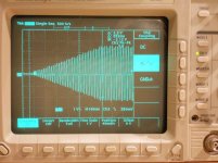
Here is the gate voltage at 2 second intervals. The first chop is the mains brown out. It has a 0.25 second period to act which usually is fine, any faster might be a problem. The next is standby or speed change which is nearly instant. Gate ripple is 1.7 mV pure sine wave. It is in phase with main output and not directly related to the mains. First 1.5 seconds is mains plug in. The Brown out action is at 23.8 VDC out of 26 VDC. The action is not unlike an ideal comparator with hysterisis of about 0.1 V. Not bad for something not asked for. If used with an unregulated output make sure the upper resistor covers exspected voltages.
The turntable I want to build a power supply for is a Thorens TD 160.
As I haven't read read the 40 pages of this thread yet, I wonder if there's someone here that also has a Thorens, and which are the steps to follow.
I have the Gary Galo article from 1/86 TAA, where he used an XP-2206 generator to feed an ILP power amp module with 60Hz and 81Hz, for 33rpm and 45rpm respectively.
This VPI project follows a similar approach?
Thanks to Pyramid and all who have contributed to this discussion.
I have almost everything I need for this project collected. The 4 Phase sinewave generator ( http://www.diyaudio.com/forums/anal...sinewave-generator-turntable-motor-drive.html ) is built and tested, three 100 Watt amplifier modules from eBay are here (identical to the ones in Ralph's post 36,) and I have 3 Antek AN0112 toroidal transformers ready. My concern is layout: how should I arrange the transformers? In post 36 Ralph arranged his co-axially, spaced about the same distance apart as the thickness of the toroid. Is this better than laying them out side-by-side. Or am I just worrying too much about possible interference among the three phases? I don't really know what the radiation pattern of the toroids is, and even if I did I might not understand what that would mean for optimum placement.
Initially, I will only be using two phases to drive the (3W) Hurst motor in my seriously modified AR-XA, but I may decide to go for a three phase motor at sometime in the future and will be well prepared for the switch.
My first version (with 3 x 30VA transformers) has them arranged vertically, simply because this was the best way to fit them in the case I had available.
My second version has a much lower profile, and the transformers (60VA this time) are arranged 'flat', on the base.
I don't think the leakage flux will have any significant effect whichever way you arrange the transformers, but, if you have a 'scope you could try either a small coil, or a hall effect sensor and see how much leakage there is.
I know I'm stepping way back in this thread, but did anyone who tried the XR2206 and LM3886 have problems with the LM3886 going into protection when first turned on? Amp seeing inrush current (short) into transformers? Is this why the resistors or NTC where added between amp and transformers?
BTW I'm going to try Pyramid's SG4.
BTW I'm going to try Pyramid's SG4.
- Home
- Source & Line
- Analogue Source
- Optimally driving a (VPI) synchronous turntable motor