If you intend to replace the AC coupling caps with another ones rated 6,3v I think it is not just a good solution. More appropriate it may be there a minimum 16v rated unipolar cap....
The AC coupling caps are to be used in AC domain, This it mean that the main appreciations and voltage rating for these caps it have to be in this respect. On a XLR output it can be voltages peak to peak up to 9v. A cap is to be rated almost three times higher voltage than the targeted voltage to be used to (AC domain). So...
6,3v rating is not good for a AC coupling cap used in that place you intend to use it.
A minimum 16v rated AC cap is a good compromise voltage/dimensions in this case. As higher the capacity, the better the results (as ESR too)...
6,3v rating is not good for a AC coupling cap used in that place you intend to use it.
A minimum 16v rated AC cap is a good compromise voltage/dimensions in this case. As higher the capacity, the better the results (as ESR too)...
Hi All
How do you measure DC offset on output.Tried it with a meter and got 845mv which seems quite high.
Took the measurement from R140 connected to plus side of CE94.
Schottky 210SQ100s in and Mundorf 22,000 uf in.will burn in and see what I think
Smiffy
How do you measure DC offset on output.Tried it with a meter and got 845mv which seems quite high.
Took the measurement from R140 connected to plus side of CE94.
Schottky 210SQ100s in and Mundorf 22,000 uf in.will burn in and see what I think
Smiffy
Hi Coris
3300uf after rectifaction.Was gonna replace it with 10,000 uf but is going any higher worth it?
Have the option of 12,000uf , 15,000uf or 18,000uf
Was quiet surprised what a diiference main caps and schottkys made.Def worth it
Smiffy
3300uf after rectifaction.Was gonna replace it with 10,000 uf but is going any higher worth it?
Have the option of 12,000uf , 15,000uf or 18,000uf
Was quiet surprised what a diiference main caps and schottkys made.Def worth it
Smiffy
Last edited:
Indeed, the bigger the capacity (filtering after rectifiers), the better the results. There are some limits because the dimensions, but as a rule, use the biggest capacity you can for the available dimensions and the voltage rating for the targeted circuits...
BTW, the voltage level you found on the outputs is not good at all. You should measure the offset right before the AC coupling caps (opposite AC coupling cap pole/leg to the one going to the RCA/XLR connector). This is measured referring to GND. As normal, you should find the offset as few +/-mV (into 10mV)...
BTW, the voltage level you found on the outputs is not good at all. You should measure the offset right before the AC coupling caps (opposite AC coupling cap pole/leg to the one going to the RCA/XLR connector). This is measured referring to GND. As normal, you should find the offset as few +/-mV (into 10mV)...
Thanks Coris
Reckon can squeeze a few more mm diameter in space but can't go much higher
than 40mm height if I want to stick top back on at some time
John
Reckon can squeeze a few more mm diameter in space but can't go much higher
than 40mm height if I want to stick top back on at some time
John
PS am I right in thinking CE106 and 107 are on the input pins of the LM317 and 337 regs?
John
John
Thanks Coris
Just found out the black gates will not fit.Having removed the caps it seems to sound a little bit better with none in.
John
Just found out the black gates will not fit.Having removed the caps it seems to sound a little bit better with none in.
John
Measuring DC offset?
Is a oscilloscope needed or just a multimeter?And I presume you do it with no music going through the circuit?
John
Is a oscilloscope needed or just a multimeter?And I presume you do it with no music going through the circuit?
John
Last edited:
No oscilloscope needed. Just a multimeter set it up on its lowest DC voltage scale.
No any playback while measurements.
Else, please see over post 1727.
No any playback while measurements.
Else, please see over post 1727.
Thanks for the help Coris
It seems to be a pain to do.Is there any point on the pcb you can measure it without flipping the board over and measuring it at the capacitor pin?
I found some 16v black gates to replace them in case its to high.
I have yet to try replacing the LM317,337 input caps but I def think It sounds better without the originals there.
Maybe the original caps where covering up the improvement of fitting the 22,000uf Mundorfs and now they are removed the Mundorfs have a better chance to shine.
Replacing the power diodes with Schottkies bumped the voltage up a bit so Analogue is now 21.7v and Digital 8.1v.
I will be looking at the SMPS soon.I have noticed the 105 seems to benefit from a mains filter.Thanks for all the help Coris.
John
Much appreciated Coris.Many thanks
R241 -0.6mv R3 -3.2mv
R140 -0.9mv R128 -3.4mv
R244 -0.9mv R141 -0.4mv
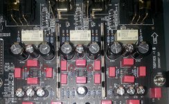
Have amp input circuit somewhere.Will pop up
Thanks again
John
R241 -0.6mv R3 -3.2mv
R140 -0.9mv R128 -3.4mv
R244 -0.9mv R141 -0.4mv
Have amp input circuit somewhere.Will pop up
Thanks again
John
Much appreciated Coris.Many thanks
R241 -0.6mv R3 -3.2mv
R140 -0.9mv R128 -3.4mv
R244 -0.9mv R141 -0.4mv
Have amp input circuit somewhere.Will pop up
Thanks again
John
Just perfect levels (for the original circuits on board).
"Have amp input circuit somewhere.Will pop up" What you meant?
Thanks Coris
Was going to put up a picture of the power amp input but as the dc offset seems to be ok will not bother
Will remove single ended 100ufs and see if amp ok with it then if ok remove the balanced output ones.
Not much left to do to analogue side after that so will start on digital supply and progress towards 9108 de coupling
John
Ta for info Coris
Amp working fine with the ouput caps removed.Noticable improvement for the removal of just one cap(and two on balanced output)
The voltage has risen with the Schottky diodes.So is 10v cap ok with 8.1v digital supply going through it?
I will do the adjustment pin to ground mod with a cap on the 317 and 337.
John
So is 10v cap ok with 8.1v digital supply going through it?
John
Yes.
- Home
- Source & Line
- Digital Source
- Oppo's BDP105 - discussions, upgrading, mods...