I have already tried with big success an 108Mhz (standard) oscillator for Ess9018, and then divided by 4 to get the clock frequency for MediaTek chip. (One may not forget that I`m running already my 95 on a 125Mhz clock for the DAC...)
It works wonderful this 108 Mhz as main clock, and I'm using now my 105 player clocked this way... Also found it the right I/V opamp. Just beautiful so far.
In fact I`m working now to find a solution to use the same main clock frequency for QDEO chip too. I actually found it the solution, I got a step forward in experimenting this, and it works. I'm only waiting now for having the right components in place, then some tests, and in the final, I intend to design a master clock kit for 105 (based for moment on an standard 108Mhz oscillator).
This project it may take a while I suppose. I will have the custom made 108Mhz SAW oscillator not before the end of this summer... But at least this is my plan for now.
PS. I think it may be designed a better (looking😉 ) stereo stage too...😀
Last edited:
BTW, I may say something (positive 😉 ) about the original clock stage of the 105 model.
As I said before, the clock stage in 105 is quite elaborated design, and now I have the prove that it is.
I was thinking (having the 95 model in mind), that placing the clock very near ESS9018 it will be better... There was not true. The best way the DAC works (when about clocking) is to have the oscillator mounted in the place the designers have originally decided. It looks like this actual design it were optimised quite much to get the best in functioning of this tandem: oscillator - DAC. I do not use the original power system for the clock oscillator (I`m using battery). Even though I have powered the oscillator by my own, its place it still be best (grounding/clock output) in the original place.
So, a positive remark here for the Oppo`s (clock stage) designers...
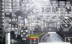
For those who want give it a try to another oscillator for DACs, here is the picture with some details:
Attachments
Last edited:
Hi Guys
I hope nobody gets their nose out of joint, by posting the feedback I am getting. I can't vouch for the results that others are getting and Ric also does them for clients and no doubt he is getting good results, as I am ceratin that Coris is. So getting additional feedback should be a good thing - the Oppo BDP-105 is a true MONSTER to upgrade, there has been nothing like it before. Thanks Oppo Digital.
By the end of this week will have done seven Oppo 105s and I have to say the feedback I am getting is unlike anything I have experienced since I picked up the first generation Philips CD Player using TDA1541A DAC and it must have been in 1986. Don't ask me how many players I have worked on, but nothing comes near to the reaction I am getting from upgraded users of the Oppo BDP-105.
Here is one I got last night after he got his on Saturday (I have toned it down a bit):
Hi Joe,
Reporting on the new Oppo 105 player, level 3.
I would like to say something intelligent or even talk in audiophile speak, but I just cannot describe it in any way that doesn't make me sound like some geeky audio reviewer. I am after all a simple man.
So lets just say its ******* awesome, holy xxxx this is left of field compared to any other player you have ever done for me - over the last 25 years that I have been coming to you.
After listening to the Oppo in your listening room, I could hardly contain my excitement and I was thinking to myself that this player would not sound as good in my own system – but no, it was xxxxxx awesome, WOW! Holy crap this is good!!!
I was up until 4am this morning trying all sorts of different configurations with my Apple TV and cable box - I was starting to keep the rest of the family up so had to settle for some movies and streaming through Pandora, which works a treat.
My Wyred4Sound DAC has been retired to my secondary system along with my Sony level 2 Terra Firma player and the FVP pre-amp and old mono blocks.
I have found that the Apple TV works better through HDMI and not with ‘optical in’ as you cannot utilise the full bandwidth through optical. The flip side is that you need to use the HDMI 1 Output to the Monitor/TV. If you do not - you don’t get the benefits of the Marvell's Kyoto-G2H video processor or the high resolution audio file formats such as Dolby digital or DTS high resolution and DTS-HD Resolution Master. Audio cannot be sent through the coaxial or optical digital audio output, thus reducing resolution. Solution is to just use HDMI to the Apple TV. I was streaming Blu-ray movies and Apple lossless files through iTunes. The sound and the movies look just as good. In fact the movies look better.
The free Oppo Remote from iTunes works a treat, once I got the player to talk to my Apple network.
Thank you Joe for another fantastic job, your hard work, your creative ingenuity and well thought-out audio design upgrades and modifications are much appreciated and always enjoyed in my home by all my family. It will get used every single day.
Regards
Paul
Maybe those additional comments about the usability will also be helpful to some.
The greatest thing is what I am doing is making people happy - and wanting to listen to music and saying they are rediscovering their library all over again. It's quite a buzz.
Cheers, Joe
But Joe, you do not change only the oscillators in this player, right? Do you replace the existing post DAC analogue processing stages with something else?
To appreciate the feedbacks it will make sense to let us know (of course not in details) some of your main mods... Else, I fully agree that Oppo 105 as it is from the producer, it have a huge potential to very high quality levels.
I have already sold few of the 54Mhz SAW oscillators, and I`m very excited to hear the feedbacks from those guys too...
I have seen recently that Epson produce some new type oscillators with 1ps or even lower jitter specifications... Not so bad!
Joe, that is the kind of response that I get from my customers that keeps me going. IF I didn't get good feedback from grateful audiophiles, then it would all be a waste of time. Keep up with what you are doing, I wish that I could hear some of those modifications in my own unit.
Everyone should know that OPPO does a wonderful engineering job. It is just that they don't get the feedback about their products, except later on, after the engineering is done. IF engineering did everything, then there would not be any need for 'tweaks and mods', and IF test equipment could measure everything that the human ear can resolve and get excited by, then OPPO and every other audio company would not need 'golden ears' and 'experienced tweakers' to make further progress in making truly perfect audio reproduction.
Everyone should know that OPPO does a wonderful engineering job. It is just that they don't get the feedback about their products, except later on, after the engineering is done. IF engineering did everything, then there would not be any need for 'tweaks and mods', and IF test equipment could measure everything that the human ear can resolve and get excited by, then OPPO and every other audio company would not need 'golden ears' and 'experienced tweakers' to make further progress in making truly perfect audio reproduction.
Congratulations Joe! That's impressive. Being an owner of older VSE Level 6.5, and 6.5+ Sonys, I know that this is some very high praise indeed if these are blowing away some of those units.
Sorry if this question is slightly OT: Might I inquire as to what kind of reaction have you been getting to your Level 2 modified 103's with the SAW clocks installed? Is it your opinion that these are these capable of (subjectively) outperforming stock 105s when modified?
Sorry if this question is slightly OT: Might I inquire as to what kind of reaction have you been getting to your Level 2 modified 103's with the SAW clocks installed? Is it your opinion that these are these capable of (subjectively) outperforming stock 105s when modified?
Last edited:
Is it your opinion that these are these capable of (subjectively) outperforming stock 105s when modified?
Thanks, much appreciated.
I have to say that the Oppo 105 is on another level above anything we have done before.
But right now, what fires me up is that we may influence the next generation of Sabre DAC equipped Oppos, the challenge is to do it without materially adding cost to the player, as the Oppos need to occupy a particular part of the market.
I may be doing myself out of future work, but right now I am sketching out some interesting things and have a discussion here about it.
So this forum should continue being interested - I will post a 'plan' about this time next week and get some feedback.
But re your question, does the 103 with SAW etc better the stock 105. Let me say emphatically YES!
It has to, as it costs more than a stock 105 - but the difference is not small. But then again, the potential in the 105 is even greater when unlocked.
The interest and the emails, phone calls, this is unprecedented. But it centers around the 105. But not everybody can afford it, the 103 is no poor cousin.
Cheers, Joe
Joe, that is the kind of response that I get from my customers that keeps me going.
Yep, then you know exactly what it feels like.
I am sketching out some ideas about how Oppo could take the player to a significantly higher level, at no added cost to manufacturing. It builds on what Oppo has already done, but the most challenging is the post-DAC circuit, and I do have something inexpensive, IC based but no feedback. Also using Epsom Toyocom SAW oscillators and get both clocks right. Really can't vouch for SAWs from other sources. They are definitely cheap enough, especially in Qty.
I have previous experience in design and manufacturing, so I am well attuned to the needs involved and cost sensitivities and practicalities. So what I want to put on the table is based on those real world requirements.
Give me about a week and I am going to sketch it out. A very simple post DAC circuit, but also very novel with a surprising twist (I think you will like it), one 8 pin SMD device per channel, low component count. The only downside is that the coupling capacitor will be necessary as it makes for the simplicity that is so important. I envision maybe a deliberate small DC offset (good to have as bias for cap anyway) - but the DIYer's will be able to later use a simple technique that can trim it away, and make it direct coupled. But the cap will stay in production units for reasons that will be obvious.
I can try it on a '105 - make that I will try it. Installation is quite easy.
The next generation Oppo could turn out to be a sensation if things work out, and I have a good feeling about this.
Cheers, Joe
Hi Coris!
Have been reading your post with much enthusiasm. Powering the clock circuit with battery is very interesting. Very low internal resistance of a battery will surely give good result. BTW, have you ever considered using super capacitor (or ultra capacitor) in the range of some 10 to 50 Farad instead of battery? Super cap is usually rated for 2,7 Volt, so can be connected serial to have 5.4V rating. For 3.3V application, it has enough margin.
Super cap has uncertainty for audio use but I hear some good result.
Hi Coris!
Have been reading your post with much enthusiasm. Powering the clock circuit with battery is very interesting. Very low internal resistance of a battery will surely give good result. BTW, have you ever considered using super capacitor (or ultra capacitor) in the range of some 10 to 50 Farad instead of battery? Super cap is usually rated for 2,7 Volt, so can be connected serial to have 5.4V rating. For 3.3V application, it has enough margin.
Super cap has uncertainty for audio use but I hear some good result.
Yes, I have considered very large capacities, too. I just bought 2 of such caps, but I have not succeeded yet to experiment this way. I think to use such large capacity (but not as high as teens F) caps for decoupling the power rails on the chip power input. I have a enough long list of experiments, and researches on different things in the field, but (of course) not enough time...
In my concept, there is a difference when using battery and very large capacities. The battery can provide very long time the power, comparing to caps, even though that caps are of very large capacity. The caps need to be "filled up" with power all the time... They do not generate as batteries... So there may be an regulator or power source before that caps. The battery is charged once and it can provide the power (quite constant on these lithium types) for very long time (on low/reasonable current use).
In this case of ES9018 DAC it may be an idea to power it from battery completely. but an quite elaborated design it may be in place to rich this task. I have in mind to take a closer look at this concept, but I do not know yet when...
Using battery to power oscillators (on few teens mA) it works just wonderful and it is very simple. I still wonder how in fact these oscillators are made inside, because they can tolerate large power supply variations (extremely slow rate in case of a battery, when discharging), without no any impact on the outputted frequency, and for the rest of the DAC system. I have used (experimental on Oppo 95) a such powered oscillator with a full charged battery, and let it work (for more than two weeks, many hour use every day) until it were stop by itself (discharged battery under the oscillator Vcc low limit). I could never notice an variation in the quality of the sound outputted. You know, when it stopped to work that oscillator, I was just listening something on the player. The sound it were just high end, and suddenly it stop everything. I was very surprised because I could not notice before it stopped working any malfunction of the DAC, bad sound and so on, which it could indicate that the battery it may be too low. Every thing it were working wonderful and suddenly stopped.
I have done this experiment with two different DAC chip types/systems. The same exceptional result.
In this case of an 3,3V oscillator there is about a Vcc lowering variation of 0,6V! It only works just fine... But when is about a reasonable use of the DAC system, and then charging the battery at once when the system is off, then the variation of tension at the oscillator power input, is in the worst case, no more than 0,2V...
All of us knows about how much work and research is done to find the lowest noise regulator solution. Ultra low noise regulators chips are created, sophisticated shunt regulators designs is used, and anyway it is not enough to get the cleanest power for very special circuits as DAC and clocks. Put a battery in place and it is just done. The difference of the sound out of a such powered clock system is only huge.
Last edited:
I am incredibly busy right now, but I have sketched out a circuit that I will post as soon as possible. I could post it now, but then not have the time for the necessary follow-ups.
I also want to actually try it on my own '105.
It will be based on a transconductance circuit/device SOIC package. Where the existing Oppo circuit needs 3 SOIC in total for two channels, this will actually only use two, as the summing of the phases takes place at the very input and no after two separate (and currently asymmetrical I/V converters that then needs another opamp to sum it together. Also, the filtering is largely passive (passive components are rather hard to force into slew - and it takes the 'heat' off the active circuitry) up to three poles (two is enough) that are buffered separately.
I will try post on Sunday.
Cheers, Joe
Super cap is usually rated for 2,7 Volt, so can be connected serial to have 5.4V rating.
Don't think that is a good idea unless to really know what you are doing. They have large amounts of dialectic absorption and they may differ from one sample to the next. So when discharged and then turned 'on' the voltage across one may see above 2.7V even if only 3.3V is fed to the series. You may try two resistors that may help to prevent the near full voltage appear across one of them. But you will need to calculate the current. Then there is the turn-on current of these caps. it can overload small SMD 3.3V regs. Also these caps, when turned 'on' first time, especially if they have been on the shelf. needs the voltage come up gradually. Not saying you can't use them, but need to be aware it is not simple.
Cheers, Joe
Joe, I can see you do have working knowledge concerning super caps. I tried to use it to my car amp and found it somewhat strange and finally took it out. For dynamic load change, they are very slow (to be charged) and cause some odd things. I just wonder how it work for the static load like clock osc. Yes, many things to be considered, for sure. Thanks for your insightful tips!
To be honest, I do not think that using caps in many Farad range to drive oscillators is a special nice/useful idea. Not even to substitute a battery to power a circuit.
Large capacity caps it may have a clue and positive impact in a device functioning when is to be used for decoupling. When about powering a device then one may chose power sources... A cap is not a power source, but an power accumulator/buffer.
The large capacities caps used for cars amplifiers, are actually huge decoupling capacities. These improve the low end of the audio frequency spectre for that car amplifiers and provide enormous instant (peaks) currents needed for that sort of high power amplifiers (special in low frequencies ranges). Such instant power needed at once by those type amplifiers, can not be provided by the car battery. That because are used so large caps as buffers in between battery and amplifier. Special circuits needed to start up charge it and for protection is a big challenge in the field. Everything become too much complicated and for doubtfully results when about using such for oscillators...
BTW, my personal opinion is that car amplifiers do not deliver at all high fidelity sound, but high power low frequencies to bump the bass elements in a very noisy environment, as a functioning car is...
At least we may back to the thread main discussion line: Oppo 105 player...
Last edited:
So other than the SAW oscillator and the Modwright mod, has anyone
found any other mods that affect this player for the better? Thanks to Coris for sharing his research in the oscillator department.
found any other mods that affect this player for the better? Thanks to Coris for sharing his research in the oscillator department.
Joe,
Do you know what the approximate impedance is that the stock Oppo 105 DAC circuit drives? I'm assuming that it is setup to drive an Op-amp which is presenting a "virtual ground" and is running as an active I/V convertor, correct?
I'm curious if in all of your experimenting if you ever removed all of the loading so that the ESS9018 was running purely in "voltage mode" instead of "current mode"? I didn't realize that it was even possible to run this DAC in "voltage mode" myself until about a week ago when I happened to try it on DIY ESS9018 based DAC kit which I just acquired. I know that this chip is supposed to measure better when run in co-called "current mode", rather than voltage mode. But my ears don't agree, and actually prefer the sound in voltage mode (I just sounds far more dynamic and "alive"), even though in "current mode" it is running a passive I/V arrangement somewhat similar to what you have described doing.
Anyways, I was just curious about what kinds of I/V configurations you have experimented with and what it was that made you go in exactly the opposite direction?
Last edited:
Joe,
Do you know what the approximate impedance is that the stock Oppo 105 DAC circuit drives? I'm assuming that it is setup to drive an Op-amp which is presenting a "virtual ground" and is running as an active I/V convertor, correct?
... I didn't realize that it was even possible to run this DAC in "voltage mode" myself until about a week ago... and actually prefer the sound in voltage mode (I just sounds far more dynamic and "alive"), even though in "current mode" it is running a passive I/V arrangement somewhat similar to what you have described doing.
Anyways, I was just curious what kinds of I/V configurations you have experimented with and what it was that made you go in exactly the opposite direction?
It may well sound better in Voltage mode because less has gone wrong and if you no longer use opamps to get a virtual earth, which is what the stock player does. That virtual earth sits at 1.65V (that is why it is virtual) and relies on feedback to achieve the effect.
But if you pull the output to ground and cause 2.1mA of offset current per phase (each 781R) and use small value 'current sense' resistors of a few Ohm, then use a very high quality amplifier (preferably without feedback IMO), then I can assure you it sounds much better than just Voltage mode. You can't do that with any other DAC that has an offset voltage - in which case you are likely to cause damage, but the Sabre DAC is different because it had a defined known output impedance that in effect is equavalent to a series resistor, so we know exactly how it behaves when we terminated at or near REAL earth conditions.
I am shortly about to post a schematic... so wait a little while and you will see a detailed example.
Cheers, Joe
Last edited:
Modding OPPO 103
Hi to all
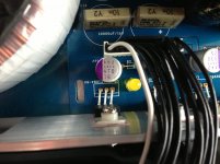
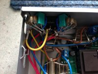
these are some photos of my modded 103.
I use this player only as a digital transport, the analogue stage was dismout.
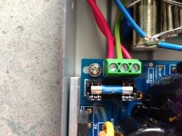
- First of all i installed a linear PSU from Jea Hong, but all caps has been changed. I installed 2 20.000müF and 2 33.000müF from Mundorf Lytic, which are quite big and made space problems. Each of them is bypassed with small wima mkp caps. Some small Rifa Pme247 were added.
The small values were changed to oscon SEPC smd with the lowest ESR known to mankind. Use only the 16v version and not more than 470müF.
Then somthing really important, the main fuse. This was changed to Padis Rhodium.
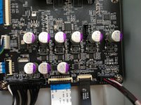
- Next thing was the smd caps on the digital board, all has been changed to the oscon SEPC 16v 470müF.
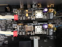
- Both clocks were changed to NewclassD / Dexas new small size Dclock Neutrino launched in may this year. Both have an own linear PSU. My experience is that the best clock without its own LPSU is nothing.
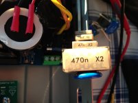
- Every PSU has its own mini power conditioner in kind of a staggered delta filter between line-neutral / line-earth and neutral-earth.
Hi to all
these are some photos of my modded 103.
I use this player only as a digital transport, the analogue stage was dismout.
- First of all i installed a linear PSU from Jea Hong, but all caps has been changed. I installed 2 20.000müF and 2 33.000müF from Mundorf Lytic, which are quite big and made space problems. Each of them is bypassed with small wima mkp caps. Some small Rifa Pme247 were added.
The small values were changed to oscon SEPC smd with the lowest ESR known to mankind. Use only the 16v version and not more than 470müF.
Then somthing really important, the main fuse. This was changed to Padis Rhodium.
- Next thing was the smd caps on the digital board, all has been changed to the oscon SEPC 16v 470müF.
- Both clocks were changed to NewclassD / Dexas new small size Dclock Neutrino launched in may this year. Both have an own linear PSU. My experience is that the best clock without its own LPSU is nothing.
- Every PSU has its own mini power conditioner in kind of a staggered delta filter between line-neutral / line-earth and neutral-earth.
Attachments
-
 IMG_0703.JPG818 KB · Views: 580
 -
 IMG_0704.JPG941.8 KB · Views: 543
 -
 IMG_0680.JPG859.8 KB · Views: 542
 -
 IMG_0681.JPG931.7 KB · Views: 529
 -
 IMG_0706.JPG923.7 KB · Views: 534
 -
 IMG_0705.JPG736.4 KB · Views: 308
 -
 IMG_0707.JPG816.9 KB · Views: 298
 -
 IMG_0677.JPG789.5 KB · Views: 253
 -
 IMG_0664.JPG720.1 KB · Views: 212
PART ONE
EXECISE: HOW TO IMPROVE FUTURE BDP-115
OTA: Operational Transconductance Amplifier
This is an exercise in how the next generation Sabre DAC fitted Oppo Player may get a significant jump in audio performance (particularly unbalanced stereo, although a balanced version can also be shown).
Manufacturing to a price is an art in itself - and business. Often products are criticised, sometimes fairly and often unfairly, that they could easily be made to sound better.
But what seems simple is often not.
For example, it is useless to suggest an alternative unless the active device is fully surface mount SOIC package - and this will be.
To me it is clear that the Oppo's post-DAC circuit presents a unique challenge, and if we want to progress, we must use something that takes us beyond the usual opamp (operational amplifier) configuration. Opamps are used because they are cost-effective and comfortable solution.
The alternative must also be cost effective, so we must keep an eye on component availability and cost. I believe this can be done, especially as the solution is an OTA based SOIC made by a major American manufacturer and this device looks to be available for a significant time into the future. Discrete active devices are almost certainly out of the question. Examine the way that the Oppos are made and you have to fit in with that - or you are out.
So top of the list: The active device has to be an 8-pin SOIC. It must be in current production and by a major IC manufacturer (and the one we will be be using doesn't come any bigger).
We know why manufacturers use opamps, they are predictable. But the use of opamps are problematic as they are feedback devices and that is not ideal, especially not inside a chassis with a significant amount of high energy HF, and not just radiating but also on the very signal coming out of the DAC. In fact, people like Charlie Hansen of Ayre has identified this as a significant contributor towards "digital sound" - and it is not difficult to figure out why. As the rise time of non-content specific noise is anywhere near the limit of the feedback to keep up, then in subtle ways (and sometimes in horrific ways) the open-loop performance of the opamp can be exposed. There is also the 90 degree feedback error caused by the internal compensator capacitor used in pretty much all opamps.
The logical answer is to use no feedback - but of course that is where the challenge starts. We need to think outside the box.
There is a certain class of opamps that can be used without feedback.
And at least one is a SOIC. I am not at this point disclose it identity, but simply state that it does exist.
Please look at the proposed schematic above. Let me say that a more complex version of this works, because I am using it. It is not available as SOIC, so the device we have in mind is similar and yet different.
But this less complex version will perform very differently to opamps - and sound far more musical, with more true instrumental colours where opamps tends to grey things out and sound thinner. The bass is also predicted to be well above the norm.
Over the next week or two, I am going to experiment with this SOIC.
In the next part, we will discuss the features and possible values of the above schematic.
.
EXECISE: HOW TO IMPROVE FUTURE BDP-115
OTA: Operational Transconductance Amplifier
An externally hosted image should be here but it was not working when we last tested it.
This is an exercise in how the next generation Sabre DAC fitted Oppo Player may get a significant jump in audio performance (particularly unbalanced stereo, although a balanced version can also be shown).
Manufacturing to a price is an art in itself - and business. Often products are criticised, sometimes fairly and often unfairly, that they could easily be made to sound better.
But what seems simple is often not.
For example, it is useless to suggest an alternative unless the active device is fully surface mount SOIC package - and this will be.
To me it is clear that the Oppo's post-DAC circuit presents a unique challenge, and if we want to progress, we must use something that takes us beyond the usual opamp (operational amplifier) configuration. Opamps are used because they are cost-effective and comfortable solution.
The alternative must also be cost effective, so we must keep an eye on component availability and cost. I believe this can be done, especially as the solution is an OTA based SOIC made by a major American manufacturer and this device looks to be available for a significant time into the future. Discrete active devices are almost certainly out of the question. Examine the way that the Oppos are made and you have to fit in with that - or you are out.
So top of the list: The active device has to be an 8-pin SOIC. It must be in current production and by a major IC manufacturer (and the one we will be be using doesn't come any bigger).
We know why manufacturers use opamps, they are predictable. But the use of opamps are problematic as they are feedback devices and that is not ideal, especially not inside a chassis with a significant amount of high energy HF, and not just radiating but also on the very signal coming out of the DAC. In fact, people like Charlie Hansen of Ayre has identified this as a significant contributor towards "digital sound" - and it is not difficult to figure out why. As the rise time of non-content specific noise is anywhere near the limit of the feedback to keep up, then in subtle ways (and sometimes in horrific ways) the open-loop performance of the opamp can be exposed. There is also the 90 degree feedback error caused by the internal compensator capacitor used in pretty much all opamps.
The logical answer is to use no feedback - but of course that is where the challenge starts. We need to think outside the box.
There is a certain class of opamps that can be used without feedback.
And at least one is a SOIC. I am not at this point disclose it identity, but simply state that it does exist.
Please look at the proposed schematic above. Let me say that a more complex version of this works, because I am using it. It is not available as SOIC, so the device we have in mind is similar and yet different.
But this less complex version will perform very differently to opamps - and sound far more musical, with more true instrumental colours where opamps tends to grey things out and sound thinner. The bass is also predicted to be well above the norm.
Over the next week or two, I am going to experiment with this SOIC.
In the next part, we will discuss the features and possible values of the above schematic.
.
Last edited:
- Home
- Source & Line
- Digital Source
- Oppo's BDP105 - discussions, upgrading, mods...