Joe:Stupid question: What precisely does the acronym "OTA" stand for in your posts above? I'm racking my brain on this one, my best guesses are clearly missing the mark (Output Transformer Amperage, or Output Topology Amperage, or Output Transistor Amperage, or ??? ).
See post #601
Joe:Stupid question: What precisely does the acronym "OTA" stand for
It's not a stupid question. There was a fair amount of detail to table, so I could have given an explanation. It stands for Operational Transconductance Amplifier, but it also has a few other labels such as Diamond Transistor. For reading an article that also discusses the history, click here.
So an OTA means voltage in and current output amplifier. But we won't be using it as an O for 'operational' because we won't be using feedback back to the "-" of the OTA. So we will be using the OTA as a Diamond Transistor stage with no feedback.
For example, "opamp" is short for 'operational amplifier where the 'operational' is a reference to feedback setting the operational point of the amplifier.
Most OTAs like OPA660, AD844 and the latest OPA860 (available in SOIC and hence the focus on it for our purposes) all includes another optional Buffer stage. So the 'Operational' part of OTA assumes that feedback will be taken back (so-called current feedback) to the "-" and that is something we won't be doing.
Hope that helps a bit, but Google "Diamond Transistor" and you will find quite a bit of info. They are NOT normal opamps even though they are opamps, some of them can be used in non-opamp modes (no feedback) and that makes them such interesting devices, so much so than ho-hum opamps. They are in fact fascinating and more flexible.
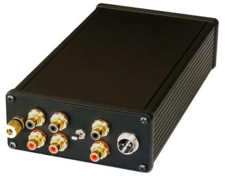
You can even use it to make a Phono Stage Preamp where the current is pushed through an RIAA network, creating the signal across the RIAA which is then buffered. No negative loop feedback at all, 1MHz bandwidth, low distortion, low noise, amazing rise and settling times (incredibly fast circuit). This was a design, MC capable, that I did with the late Allen Wright:
Yep, OTAs and Diamond Transistors, I like them, I am familiar with working with them and they appeal to me.
Cheers, Joe
.
Last edited:
I might like to try bypassing the IEC, or getting a better IEC.
Just be aware of the transformer switching which has Primary windings in either parallel (115V) or series (230V) - the SMPS board can handle both 115V and 230V (and everything in between), but don't overlook the transformer.
.
THIS IS GEETING SERIOUS NOW!
I thought about it and made a decision...
I have just brought in an Oppo 105 for one purpose only - I am going to do a player as per earlier discussions here and post everything I do, everything will be documented.
What will be done to this '105 would be - stereo channels only - what Oppo could have done at no extra cost if done at the manufacturing stage:
1. Post-DAC circuit using OPA-860 for stereo channels - and regulators powered from the existing 15B rails, down to 5-6V.
2. Murata 10uF/25V SMD (6) on the DAC in place of electrolytics
3. Clocking 54MHz with a SAW oscillator, then deriving 27MHz from that via 4040 (NXP 98MHZ version) divider.
4. Still retain the Silma output caps, but perhaps give them a small positive
5. Instructions how to null the output, so that Silmics are not required. Both 4 & 5 are documented as we have the 'Oppo with' option and the "DIY" option where caps can be dispensed with. It would be interesting to get feedback, to what extent is the Silmics audible (to put it bluntly, what is lost?).
I have all the bits in now except one. The adaptors for fitting SOIC into DIL8 sockets - got some, but were too wide - have ordered correct size and should be here shortly.
ANYBODY CAN REPLICATE ABOVE.
The one component hard to source may be the 54MHz SAW oscillator - but Coris has some and while I do too, I use them at a fair rate and four months delivery time means I have to keep a lot in hand.
Please wait a little longer... only a little time...
Cheers, Joe
Just be aware of the transformer switching which has Primary windings in either parallel (115V) or series (230V) - the SMPS board can handle both 115V and 230V (and everything in between), but don't overlook the transformer.
Not looking to do anything fancy here. Can you identify the connector that connects to the board?
Len
I wonder whether some one can identify the plastic connector that carries the power directly from the IEC to the circuit board. I might like to try bypassing the IEC, or getting a better IEC.
Thanks,
Len
I`m not very sure what you refer to about IEC... It seems to me that you think about the power in (from outlet) stage.
From my part, I will recommend to everybody to do not touch this power in (to switching PSU) stage of the player. There is not any improvements to be done in this area. Main power input and AC filtering is definitely not something one may work around on this device. The important improvements come from special care in better filtering and noise removing from the DC power resulting from player`s switching PSU (+5v), and from the analogue PSU.
Is to be named also here that huge improvements come from modifying crucial circuits in audio/video signal processing. The areas one may focus on are: clock system for whole player, the power system for the clocks, and post DAC analogue signal processing (special for stereo stage).
Last edited:


Just a quick question - the Oppo 105 uses a 54MHz oscillator (X1) directly, as far as I can tell, directly into the Stereo Sabre DAC. But the clock signal to the Multi-Channel Board/Sabre DAC seems to be going through a Buffer (clock Buffer U7). I think it is a SOT353 (or perhaps SOT555) package.
Something interesting happened, when increasing 54MHz to 100 MHz, the Stereo Sabre DAC works fine all the time, but there is a chance that the Multi-Channel becomes intermittent because it does not see the clock signal directly in its Sabre DAC. The Buffer may not be rated to handle 100MHz.
I just thought others may need to be aware of this when modifying the 105 - that increasing clock frequency may mean a problem on the Multi-Channel side, where it just drops out, period.
I tried to read the number on that U7 Buffer. It is very faint, but it looks something like "NO10" - but searching has not shown up anything.
I would love to know the spec of "NO10" - there is a similar Toshiba Clock Buffer that was rated to 80MHz only. So using 100MHz and we are likely to loose clock signal.
Cheers, Joe
.
The U7 is not a buffer, but an converter unbalanced (oscillator out) to differential. Or an differential transmitter, to be more correct. It is rated to 200Mhz. The same is the (paired) differential receiver on the other side (multichannel DAC). The clock signal from 54Mhz oscillator is transported differential (through connector) to the multichannel DAC.
I run on 108Mhz clock, and the multichannel is working very well. No dropout.
What is quite special with this circuit is that is very sensitive to any imperfections of the oscillator outputted signal (level, harmonics, etc). The design of the circuit is optimized quite well to work as it is (oscillator placed in the original place). So, much care to implement the new oscillator with very short traces/wires, as much as possible connected to the original tabs (Vcc, GND, out).
The U7 is not a buffer, but an converter unbalanced (oscillator out) to differential. .
Yes, I can see it is balanced output with a DSO - but that still makes it a buffer. From what I can see it only feeds the multi-channel side, right?
Just odd that they do it for the multi-channel alone, but I think I know why. This clock signal has a more convoluted path, it has to go through the connector, ribbon wire etc, plus more PCB track length, so balanced should be less sensitive to contamination. Whereas the oscillator's direct output is much more adjacent to the Stereo DAC. I assume this is why Oppo did it this way? Your thoughts?
You say that U7 is rated at 200MHz, do you know it's identity? Have I missed a post with that info?
Cheers, Joe
Last edited:
It is right, the balanced/differential transmission of the clock signal is only for the multichannel stage. This is a clever idea. My supposition is that they did try to do it so for this model, before choosing of a more elaborated clock system for the whole player. One can see that it were placed a micro BNC footprint in to the main processor clock design, but nothing planted there yet... So, I expect the next model it may have a more sophisticated and maybe unified clock system. 54Mhz clock for DAC is not choosen just by chance... But the DACs perform better anyway at higher frequency...
I have identified that chip, and even downloaded its data sheet. It were quite intensive Google search... The main problem is that I can not find right now that file or paper. BTW, that chip is marked in my device as NO1Q. My main computer is waiting for a new motherboard, so I can not use it for moment. I do hope this information it may be there. But I can well remember that the differential line transmitter bandwidth is rated 200Mhz. Anyway, if you may place/solder an 100Mhz oscillator right on original tabs of the old one (using 2-3mm long wires), then it should work very well the multichannel stage.
When I will find that datasheet, I will publish it here...
Last edited:
It is right, the balanced/differential transmission of the clock signal is only for the multichannel stage....
Thanks Coris. Yes, I also thought that U7 was NO1Q - but tried hard and got no search result, so well done if you find a datasheet as I could not. Let us look at it when you can.
On the bench, I have a single 54MHz SAW to Sabre DAC(s) and 27MHz via 4040 chip going below to the MT chip. Works well on the bench. Now working on the post-DAC circuit and will post it later this week.
Do you think that single 54MHZ/27MHz SAW solution works better than separate SAW clocks? I am yet to hear it, but will soon.
Cheers, Joe
.
Hi Boky
Yes, I did survey TI's website... and this is the one? Thanks.
Not sure I would call it (OPA860) a "solution" - for what? Really, it is an interesting exercise in what Oppo could have done or might do in the future. So it is an exercise, that's all, but one that may be revealing. Sometimes you have to be brave and stick one's neck out and be prepared to take flack. I can take it.
If only OPA660 was still available.
Like my revised signature... hope it meets your approval. The OPA860 still uses feedback in the buffer, but at least it is current feedback a la AD811 - and yes, I agree, that too is a goodie.
Cheers, Joe
PS: And how about dropping in sometime?
Last edited:
I run on 108Mhz clock, and the multichannel is working very well. No dropout. .
I have an interesting experiment going, just as I type this: There must be no series resistance on the output of the SAW oscillator, or the balanced/driver/buffer will likely conk out. The Oppo 105 I have going right now, I can turn the multi-channel Sabre DAC "on" and "off" while playing music from an SACD (or any disk or source), like it was a switch or mute. Really a strange experience/experiment, turning music on and off like that, just by making to wires touch.
So, as you said earlier, the SAW must go straight into the pad of X1 that was removed. The stereo DAC never stops working, though.
Cheers, Joe
.
There may come some noises over the clock signal or on the transmission line when you touch the wires, which it alter signal level/quality, so the multichannel DAC it loose the clock (on/off...). You may scope what you have there to get a better understanding...
I experimented earlier with the oscillator placed right to the stereo DAC pin of 105 (like I did on 95). I have to say that was not good results... There may be a new design of 105 PCB which it may differ here...
BTW, my actual working 108Mhz oscillator is not (yet) a SAW one. I have got the 108Mhz SAWs, but I get not yet the necessary time available to make the change.
Anyway, very short connections for the new oscillator placed in the original place, it seems to leads to best result...
- Home
- Source & Line
- Digital Source
- Oppo's BDP105 - discussions, upgrading, mods...