Member
Joined 2009
Paid Member
This was from me 🙂
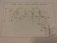
Yes, I reverse engineered a Don Garber amp, generating this schematic, and found it matched with Lipman. FYI - I recently painted a chassis which will be used to build my version of this classic.
Yes, the 25K Mills resistor marked R7 is not an appropriate plate load for the 6SF5. That load is 100K in Lipman, 150K in the Shishido.The drawn schematic doesn't.
Lipman's R7 is 25K/10W and goes to B+, not to the 6SF5. That's a more likely place for a Mills!
Nobody has mentioned the original Loftin-White circuit; here's an article on it:
http://messui.polygonal-moogle.com/valves/VR199108.pdf
http://messui.polygonal-moogle.com/valves/VR199108.pdf
Thanks for posting the link. I was wondering about a possible relationship with the Loftin-White circuit and had started looking around for more information but there was such variety in circuits posted online that I began to think "Loftin-White" was being used as a general synonym for direct coupling.
Some implied that capacitive or R/C coupling of the two cathodes was part of what it means to be a true L-W circuit. I get the sense from reading the article you posted and also articles from 1930 issues of Radio News (see January through July here) that it is mainly the elimination of any capacitive coupling by setting bias voltages with resistance. Would that be its defining characteristic?
Another question that comes out of reading about the Loftin-White circuit is the emphasis on stability frequently mentioned together with its immunity to the destructive effects of pulling the input tube. Based in large part on what I learned from the Paraglows years ago, I have built a number of directly coupled circuits and have never found stability to be a problem ( Nor have irresistable impulses to pull a tube in the middle of Beethoven's 5th! : )
Thank you !
Last edited:
Member
Joined 2009
Paid Member
Oh yeah, looks like a drawing error, is supposed to be B+ not gnd at the bottom there.The drawn schematic doesn't.
My fault! I knew I should have thought about the wording a little more but wasn't sure how to do it without it getting cumbersome and I was in a hurry.
I meant the difference between the drawing you posted and the Lipman. R-5 in Lipman's is in the same position as R7 in yours. R-7 in Lipman's doesn't have an equivalent in yours, making it (in my amateurish view) fundamentally different. My thinking is that if yours is a part for part representation of the Fi then the Fi isn't a Lipman.
I drive my friends nuts like this but I'm not good at understanding / categorizing complex things and have to make these distinctions in order to stay sane. Sorry!
Like the WE Model 91, the term Loftin-White has been diluted to mean little more than direct-coupled single ended. (It happens everywhere. Any alcoholic drink in a conical glass has become a "martini" ...)Thanks for posting the link. I was wondering about a possible relationship with the Loftin-White circuit and had started looking around for more information but there was such variety in circuits posted online that I began to think "Loftin-White" was being used as a general synonym for direct coupling.
Some implied that capacitive or R/C coupling of the two cathodes was part of what it means to be a true L-W circuit. I get the sense from reading the article you posted and also articles from 1930 issues of Radio News (see January through July here) that it is mainly the elimination of any capacitive coupling by setting bias voltages with resistance. Would that be its defining characteristic?
Another question that comes out of reading about the Loftin-White circuit is the emphasis on stability frequently mentioned together with its immunity to the destructive effects of pulling the input tube. Based in large part on what I learned from the Paraglows years ago, I have built a number of directly coupled circuits and have never found stability to be a problem ( Nor have irresistable impulses to pull a tube in the middle of Beethoven's 5th! : )
Thank you !
I do think the multi-tapped resistor across the power supply is the most distinctive feature. The Lipman circuit abandons three of the taps (large driver cathode resistor with negative supply, screen voltage tap, and driver B+ greater than cathode voltage for a higher plate load) so it's not really the same thing. Only the tap to the 2A3 cathode remains.
That resistor chain does improve the stability of bias points as the tubes age, or are replaced with similar-but-different tubes. This has always been the issue with direct coupling. It was a very clever idea at the time. But it wastes power - today we do it with trimmers and servo circuits.
Ejam, thank you for that considered reply. I've understood from the beginning that we want to design so that the space between the grid lines along the load line are even. However, I'd never heard the term compression used to describe the non-linear areas even though I've been doing this hobby for several years now, so thank you. It's also interesting to think about using the distortion generated in the input and output stages as a mutually canceling dynamic.jdrouin
Sorry for the late reply, am on the other side of the world, so your awake, am asleep and vice-versa. Compression is merely a term to describe the bunching of the curves to the right of the operating point. If you look at the right side curves, you'll see them getting closer together and to the left of the operating point, further apart. Now if the curves were evenly spaced, then you would have no distortion. However in our case as the musical signal moves along the loadline, left and right, it for a better term compresses, as the signal becomes more negative and, expands as it becomes more positive, hence the generation of distortion and in the case of tubes mostly second harmonic distortion. Where it becomes particularly bad is when the Vgk curves rapidly change curvature when operating currents are low. You'll see below 0.2mA for the 6SF5 the curves bend greatly and above 0.5mA they straighten and the spacing becomes more uniform. So when choosing an operating point, best to avoid that non-linear region. That is the standard engineering approach and quite sound. Now in the black arts of tube design, this added distortion maybe used to advantage as the 6SF5 inverts the signal (and its distortion) being a common cathode stage. Now the 2A3 generates distortion as well. The trick is to get an input tube that has a distortion profile matching the output tube's. By adding the inverted distortion to the distortion, hey presto they cancel, at least in theory. Perhaps this is what Don Garber found with the 6SF5. The 6SF5 is similar to the 12AX7, 6SL7. 12BZ7 tubes in distortion profile and I've had no luck with them using a 2A3. Mine you I haven't tried every combination and no doubt someone on diyaudio will pull a rabbit out of a hat. I can say that the 12AT7 and the 6J6 worked this magic with the 2A3. Anyway, enough from me, hope this helps. For what its worth, I have never been able to make Garber's amp design work, always thought there were deliberate mistakes in the component values to throw copiers off.
Last week I breadboarded a 2A3 amp using 1/2 a 6SL7 as a simple voltage amp in each channel. It sounds surprisingly good. If I'm able to find another 6SL7 cheaply enough, I'll try an SRPP input stage.
Otherwise, I'm going to try breadboarding the Lipman/Fi circuit using a single rectifier tube with separate power supply rails in each channel, like Garber did on the stereo version. I'll use minimum 500V caps since the B+ will need to be close to 450V. However, I don't currently have three 22uF caps available per channel, as Garber/Lipman used. Do we think it would be a problem if I use a 15uF, 47uF, and 100uF in each channel?
JdrouinEjam, thank you for that considered reply. I've understood from the beginning that we want to design so that the space between the grid lines along the load line are even. However, I'd never heard the term compression used to describe the non-linear areas even though I've been doing this hobby for several years now, so thank you. It's also interesting to think about using the distortion generated in the input and output stages as a mutually canceling dynamic.
Last week I breadboarded a 2A3 amp using 1/2 a 6SL7 as a simple voltage amp in each channel. It sounds surprisingly good. If I'm able to find another 6SL7 cheaply enough, I'll try an SRPP input stage.
Otherwise, I'm going to try breadboarding the Lipman/Fi circuit using a single rectifier tube with separate power supply rails in each channel, like Garber did on the stereo version. I'll use minimum 500V caps since the B+ will need to be close to 450V. However, I don't currently have three 22uF caps available per channel, as Garber/Lipman used. Do we think it would be a problem if I use a 15uF, 47uF, and 100uF in each channel?
Thanks for your reply. Just to qualify, when I said I had no luck with the 12AX7 etc, I was referring to a direct coupled circuit. Personally, the best results I had was using a 5695 in a SRPP, LC coupled (grid choke) to a 2A3. I started off with Gordon Rankin's Baby Ongaku and modified it by replacing the 12AT7 with the 5695 and the RC coupling with LC. Very nice result on my system. Regarding the 6SL7, good tube in my experience. However, I usually like more that 1mA driving the 2A3 hence my 5mA for the 5696 after listening. Some say 20mA is a minimum, and you get into that bigger is better thing. Remember audio is a recipe not a race.
BTW, I reckon Garber went for the 22uF caps as a sonic choice. A conversation I had with him 20 or more years ago was he wanted a fast power supply by using smaller caps (what ever that means). I suspect that he used 22uF caps as they don't present current in-rush problems for your tube rectifier. Try your combination and if your happy with it, problem solved. The 22uF 630VDC Solen are not too expensive (around $12 each) or I use the ASC 20uF 440VAC oil caps for ($15 each) if your not happy.
Just before I sign off, a word of advice from 30 years of doing this, trust your ears and not others and when you make something that sounds good, sit back, relax and enjoy the music, otherwise you'll spend way too much time and money chasing your tail like I did.

Some of you will know that I've been trying various published 2A3 circuits in another thread and recording the results: https://www.diyaudio.com/community/threads/developing-a-2a3-set.389161/.
I'm now at the point on the list where I'm going to work on the Lipman/Garber direct-coupled circuit using the parts I have to hand. That means the power supply caps will have different values than the 20uF units in the original schemo, but it shouldn't affect the voltage. I've been playing around with the circuit and operating points in LTSpice and learning a lot.
The Lipman circuit uses a PT with an HT winding of 325-0-325 into a 5Y3GT, single channel. In LTSpice, at voltages I guesstimate to be in the range of 650Vct into a 5Y3GT, it's really hard to get the 45V across the 100K input plate load/output grid leak resistor without excessively high current in the 2A3. But with a B+ of say 365V or 385V, the dissipation wattage is within a reasonable limit of the resistors spec'd in Lipman.
On the other hand, when we raise the voltage higher to what has been speculated in this thread to be the ~450V B+ of Garber's circuit, the dissipation is so high (about 8-9W on the variable resistor, for instance), the spec'd parts don't really leave enough headroom to prevent running at very high temperatures (I don't like that).
So, I'm going to breadboard the original Lipman circuit with one channel, into a dummy load instead of a speaker, and take voltage measurements as a starting point. I have a PT with a 660Vct winding, which is a bit high. My wall voltage tends to sit at 123V these days. So, if I use the 125V leads on the PT primary instead of the 120V leads, that's:
That 6 hundredth of a volt is a little hairy, but for a DIYer that should be close enough to the original.
I'm calculating this based on the notion that PT windings relate to one another in a fixed ratio. If anyone sees a problem with it, speak now or forever hold your peace. 😆
I'm a bit busy at the moment so it might take a few days to report back.
I'm now at the point on the list where I'm going to work on the Lipman/Garber direct-coupled circuit using the parts I have to hand. That means the power supply caps will have different values than the 20uF units in the original schemo, but it shouldn't affect the voltage. I've been playing around with the circuit and operating points in LTSpice and learning a lot.
The Lipman circuit uses a PT with an HT winding of 325-0-325 into a 5Y3GT, single channel. In LTSpice, at voltages I guesstimate to be in the range of 650Vct into a 5Y3GT, it's really hard to get the 45V across the 100K input plate load/output grid leak resistor without excessively high current in the 2A3. But with a B+ of say 365V or 385V, the dissipation wattage is within a reasonable limit of the resistors spec'd in Lipman.
On the other hand, when we raise the voltage higher to what has been speculated in this thread to be the ~450V B+ of Garber's circuit, the dissipation is so high (about 8-9W on the variable resistor, for instance), the spec'd parts don't really leave enough headroom to prevent running at very high temperatures (I don't like that).
So, I'm going to breadboard the original Lipman circuit with one channel, into a dummy load instead of a speaker, and take voltage measurements as a starting point. I have a PT with a 660Vct winding, which is a bit high. My wall voltage tends to sit at 123V these days. So, if I use the 125V leads on the PT primary instead of the 120V leads, that's:
- 660 / 125 = 5.28
- 123 * 5.28 = 649.44 Vct
That 6 hundredth of a volt is a little hairy, but for a DIYer that should be close enough to the original.
I'm calculating this based on the notion that PT windings relate to one another in a fixed ratio. If anyone sees a problem with it, speak now or forever hold your peace. 😆
I'm a bit busy at the moment so it might take a few days to report back.
Attachments
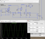
Gee, thanks! Super helpful! So, in post #33 you build the "updated" schematic that Garber had given to a customer, and which is available online (and attached here). Where you have 1K->4K in the bias set network, Garber has a single 5K resistor. According to your voltages, that 5K is dissipating 203V / 5K = 40.6mA ^2 * 5K = 8.24 watts. How's the heat on the resistors there? A single 5K 25W resistor would be only 3x the dissipation. And you've got 61V across the 100K resistor.These were the numbers when I built it exactly to that schematic.
When I model your "Updated" schematic in LTSPice, it shows the 2A3 running at about 278V/28mA.
In the original schematic, where you measure 169V on the 2A3 cathode, the bias network is dissipating about 4.76 watts. At least from what I can read. Your variable resistor at R3 is set to the full 5K, correct?
In the original Lipman circuit, I can sort of get close to your measurements in LTSpice with 3.5K on the variable resistor in the bias network. 2A3 is at about 208V/20mA (you measure 207V).
I'm struck by how both these designs run the 2A3 with much lower current than we tend to do today. One case runs it at much higher plate-cathode voltage, and the other much lower.
What were your impressions of the sound quality (if any) in the two circuits?
Thanks again for sharing. This is so fun to think about.
Attachments


OK, so I started thinking about using the various PTs and rectifier tubes that I have lying around, in order to try and make the voltages in Old Big's schemos. Re: the original Lipman, I speculated about using a 400Vct transformer with a choke-input 83 rectifier in each channel. That probably wouldn't produce high enough voltages. But nonetheless, the idea of a nice glowy gas rectifier tube made me wonder if it's possible to use something like a 0D3 to regulate the bias network.
The 2A3 in this LTSpice model certainly didn't like that (4mA plate current and clipping galore), but anyway it's fun to speculate about. I tried to produce the voltages in Old Big's measurement to model the behavior. 😆
Anyway, it would be fun to make a super glowy version of this circuit, as long as it sounds good.
Attachments
The results in post 33 I'm showing 40ma on the 2a3 (203÷5k). If I built this amp i would use 50 watt cathode resistor as I was using a 10 watt 1k and a 25 watt 5k adjusted to 4k. The amp sounded very good. I'm waiting for you to build it and hear your impression.
I think your going to need about 1200vct to run a choke input filter to get to 480 b+.
The Lipman amp just didn't have enough output for me.
I think your going to need about 1200vct to run a choke input filter to get to 480 b+.
The Lipman amp just didn't have enough output for me.
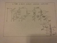
I built the Shishido version and it is very stable regarding operating voltages. The voltage divider (22k & 3k) resistors help lessen the stress at start-up and provide a reference for the 2A3 bias voltage. Of all the direct-coupled circuits I have seen, this one makes the most sense and probably has the most stability. The Robin & Lipman circuit (Garber) looks stable too, but it's just configured differently.
I used a surplus power transformer, but many will work with a secondary voltage of 350-0-350 or 375-0-375 @ 100mA (mono) or 200mA stereo. If you need to lower B+ add a power resistor directly after the rectifier before the first capacitor.
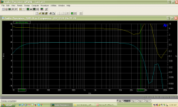
I initially used a Lundahl output transformer, but have since put in a Hammond 1627SE. Both sound great and the Hammond has better low-end which is good for my three-way horn speaker that is >100dB efficient.
I used a surplus power transformer, but many will work with a secondary voltage of 350-0-350 or 375-0-375 @ 100mA (mono) or 200mA stereo. If you need to lower B+ add a power resistor directly after the rectifier before the first capacitor.
I initially used a Lundahl output transformer, but have since put in a Hammond 1627SE. Both sound great and the Hammond has better low-end which is good for my three-way horn speaker that is >100dB efficient.
Attachments
-
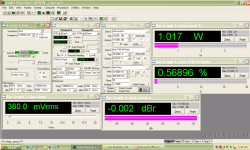 Shishido 2A3 Mono_1 Watt-8 Ohm_1kHz.png101.7 KB · Views: 221
 -
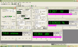 Shishido 2A3_30Hz_Rated Power.png104.3 KB · Views: 117
 -
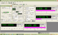 Shishido 2A3_1kHz_Rated Power.png100.5 KB · Views: 110
 -
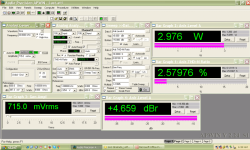 Shishido 2A3_20kHz_Rated Power.png105.1 KB · Views: 108
 -
 Shishido 2A3_Power Response_3.5 Watts.png37.1 KB · Views: 108
 -
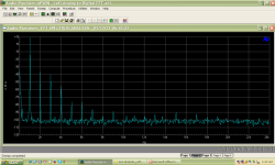 Shishido FFT_1 Watt.png39.2 KB · Views: 113
 -
 Shishido 2A3_Frequency Response and Distortion.png37.8 KB · Views: 209
 -
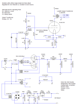 Loftin-White_Shishido SE 2A3 Mono Direct Coupled_v1.1.0_021223.png23.8 KB · Views: 280
@jdrouin I've been following this thread closely and finally have the parts - at least the pricier ones - for a 2A3 build. Curious to know if you built or sorted the operating voltages in the Fi 2A3 schematic (the original or the upgraded).
I've been back and forth between a direct coupled build like the Fi or Loftin White or a cap-coupled amp like Rankin's Baby Ongaku.
Were the Spice models accurate? And to be sure I'm reading correctly, you had 495V B+?When I model your "Updated" schematic in LTSPice, it shows the 2A3 running at about 278V/28mA.
I've been back and forth between a direct coupled build like the Fi or Loftin White or a cap-coupled amp like Rankin's Baby Ongaku.
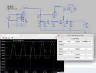
The attached direct coupled 300B should have better performance. Using the plate choke would provide more clean signal driving the 300B. Also, the circuit is fail safe for the 300B in case the driver tube fails or loose from circuit.
The circuit can be easily modified the 300B to 2A3.
Happy New Year,
Johnny

The circuit can be easily modified the 300B to 2A3.
Happy New Year,
Johnny
- Home
- Amplifiers
- Tubes / Valves
- Operating Points of Fi 2A3 / 3 Tube 3 Watt Direct Coupled Amplifier (Lipman)