@jdrouin Curious to know if you built or sorted the operating voltages in the Fi 2A3 schematic (the original or the upgraded).
Were the Spice models accurate? And to be sure I'm reading correctly, you had 495V B+?
Hi joneci,
I breadboarded the original Lipman and the two Garber circuits (they're all virtually the same). I don't recall exactly what the voltages were, but B+ was way up there. I found the performance lacking because the 2A3 was running at too low a current and voltage point. You can follow my travails at this thread, where I did post the values from the Fi circuits (I think):
https://www.diyaudio.com/community/threads/developing-a-2a3-set.389161/
At one point, I used LTSpice to tweak the Lipman/Garber circuit and developed a version that sounds much better to my ears because it runs the 2A3 at one of the normal operating points, about 270Vak/50mA (I think it's actually like 727V/52mA). I named it after my late aunt Lorraine and posted the schematic, which is also attached here.
It sounds pretty good running extremely sensitive Lowther single full range drivers in a small room. However, it could use an input tube that delivers more current than the paltry 0.55mA that the 6SF5 is putting out in this cofiguration. The folks who commented on the thread linked above say that 2A3 really needs at least 8-9mA of drive current to avoid slewing problems.
That said, I really like the immediacy and vibrance of the direct-coupled circuit, and have been playing around with designs in LTSpice. For instance, attached here is one I thought up on my bike ride today, using a paralleled, choke-loaded 6N7 to deliver 14mA of current to the 2A3, with a stacked power supply that will allow the 6N7 to run at the recommended operating point in the datasheet (294Vak/7mA per section). It has an input sensitivity of 1V, and would be realistic to use as a 2-stage integrated amp.
I'm not familiar with the Baby Ongaku but know of its reputation. For that reason, I'd probably pick it over the Fi direct-coupled design. With cap-coupled designs, my favorite by far was the SRPP 6SL7 into 2A3 (also in the thread linked above), a surprisingly good performer with only 0.7mA of drive current (also posted in the thread above).
If you haven't made yourself a breadboard, it might be worth doing so in order to try different designs and learn about what you like before committing to a final build. I'm very glad that I've been taking the time play around and experiment.
Attachments
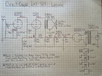
Assuming 60ma through the 2A3, Vr1 is 162V.This is a 2A3 adoption of kmtang´s 300B circuit. 5842 120v/10mA, 2A3 255V/60mA View attachment 1254034
V1 at max of 38ma through 220 (R5) is only 8.36V below the cathode of the 2A3.
This is not going to work.
As TheGimp wrote, with these parameters not working.
It's not DRD (Direct Reactance Driver by Jack Elliano), one resistor is missing.
There is Excel for calculating "classical" DRD layout values.
Sample for 5842-2A3 SE (DRD):

It's not DRD (Direct Reactance Driver by Jack Elliano), one resistor is missing.
There is Excel for calculating "classical" DRD layout values.
Sample for 5842-2A3 SE (DRD):
Attachments
Last edited:
It's fair to ask why folk are exploring this topo, with its very poor driver stage loadline, operating point and wasteful output stage cathode resistance (cathode bias plus driver stage anode voltage), for no real purpose. Retro-style, fashion?, but a big performance penalty. Better choices are available to us 90-odd years on.
Sorry to be grumpy, but needs saying,
Chris
Sorry to be grumpy, but needs saying,
Chris
Sorry, Gimp and euro21, I think you have may have missed the simple fact that the 156C has a series resistance of 3.7kohm?
Probably the 5842 and the 2A3/6B4G aren´t good together which the .four indicates. Will try the E88CC as I have used them before.
Great spreadsheet euro21, adjusting it for 2A3 makes R1 approach zero. Using it give a R1 of 50ohms which equals the heater 100 ohm resistors in parallell. Also we seem to have different 5842 models.
These are the voltages currents in the circuits again, also added the file to play with:
Attachments
Last edited:
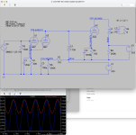
Sorry Paul, mea culpa. Adjusted Ck, this one should be in the ballpark of OK. Also changed the tube model to heater style.

Last edited:
Probably the 5842 and the 2A3/6B4G aren´t good together which the .four indicates.

Try these methods in asc:
The distortion values are believable.
I'm not a fan of harmonic cancellation, one mistake covers another, it doesn't fix it.
Attachments
Last edited:
BTW ultrapath topology (C2 from B+ to cathode) design disadvantage is the ultraclean PSU necessity.
The PSRR about 20dB, so general PSU designs are unnecessary.
The PSRR about 20dB, so general PSU designs are unnecessary.
Thanks euro21,
"The distortion values are believable.
I'm not a fan of harmonic cancellation, one mistake covers another, it doesn't fix it."
The simple .four I ran gives good enough figures, still it indicates that the output tube isn´t the most linear, which already both measured and published Ia/Ua curves from the manufacturers indicate.
Would not build a "free lunch"-circuit myself.
Have been tempted to try a PP-version Dave Slagle and I discussed many years ago, though.
Wonder how a slight Schade feedback over the tube would sound?
Interesting to find that not much have happened here, since coming back to diyaudio after more than ten years.
I think the attraction is the direct coupling part. I used to be obsessed with DC amps, somehow thinking not having a cap in the signal path is the key to audio nirvana."It's fair to ask why folk are exploring this topo"

Chris, directdriver -- Yes, I'd always done cap-coupled amps and wanted to try something different. Direct-coupled simply seemed interesting. Figured I would begin by breadboarding/evaluating established designs as a starting point for developing my own (which I've been doing in the thread linked above). This thread was initially a plea for information on operating points that was difficult to find online, to help me get started. I also wanted to document the op point information for other builders to use.
Excellent. Draw an actual loadline for the driver in question, and see for yourself. No need to trust random folk and their (our) prejudices - seeing is believing. You'll see my objection to the whole scheme, that the operating region is way off down and to the right, where things are distorted by being in the knee of the curves. But best to see for yourself.
These early designs were in response to parts availability and cost in their era. Even small capacitors were expensive, but inductors could be homemade and were otherwise more affordable than today (relatively, of course). Today, almost perfect capacitors are a few bucks, and for coupling use, with no signal voltage across themselves, cannot generate distortion. The cult of magic coupling capacitors would not survive even the most rudimentary blind test, yet it lives on in discussion groups. Worse things could happen I guess.
(One worse thing would be if actual performance were sacrificed to the cult.)
All good fortune,
Chris
Gave your comment a thought overnight and realized the "free lunh"-concept with choke is not up to date, just a funny idea to play with. For direct coupling with the smallest effort, a 2xNMOS CCS from filtered B+ would be the simplest task, instead of a bulky, expensive and hum sensitive choke. The CCS is then easily fine tuned to get the correct working point for the 2A3/6B4G. The 6SF5 also has far to much gain and to high Ri, even if it seems to have very good linearity. A driver with 20-40 mu should be enough.BTW ultrapath topology (C2 from B+ to cathode) design disadvantage is the ultraclean PSU necessity.
The PSRR about 20dB, so general PSU designs are unnecessary.
Does the Lipman really allow enough swing over the driver anode resistor?
Just for fun I played with local/schade feedback around the 6B4G and a MJK sand driver, but that might be something to discuss in another thread after listening to it, as it is being built by a friend of mine.
Attachments
Last edited:
Yes, output stage bypass capacitors should be brought to the driver's B+ supply for best noise immunity.BTW ultrapath topology (C2 from B+ to cathode) design disadvantage is the ultraclean PSU necessity.
The PSRR about 20dB, so general PSU designs are unnecessary.
All good fortune,
Chris
Using plate choke for the driver has its advantages. Firstly, the distortion is less than resistor load. Secondly, it could provide much higher output signal than resistor and CCS loads. Of course, the frequency response isn't perfect but it is good enough when high inductance and low capacitance plate choke is used.
Johnny
Johnny
Thanks for your insight. It was super helpful to review the thread you linked to and hear your experiences. After considering the response and anecdotes, I think I will proceed as intended with the Baby Ongaku. I've got almost all the parts but have always been mesmerized by the sound and relative simplicity of a direct coupled circuit... perhaps a Fi 2A3 or something similar build will be my 2025 winter project. This thread will serve as a great reference.That said, I really like the immediacy and vibrance of the direct-coupled circuit, and have been playing around with designs in LTSpice. For instance, attached here is one I thought up on my bike ride today, using a paralleled, choke-loaded 6N7 to deliver 14mA of current to the 2A3, with a stacked power supply that will allow the 6N7 to run at the recommended operating point in the datasheet (294Vak/7mA per section). It has an input sensitivity of 1V, and would be realistic to use as a 2-stage integrated amp.
- Home
- Amplifiers
- Tubes / Valves
- Operating Points of Fi 2A3 / 3 Tube 3 Watt Direct Coupled Amplifier (Lipman)