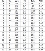
I am trying to figure out a good operating point for 6SN7. Morgan Jones says it is more linear at higher Ia. I tested my Tung-Sol 6SN7's with a common cathode circuit using Morgan Jones' best constant current source in the anode. I measured distortion with WinAudioMLS and a good sound card. The results are in the spreadsheet.
It looks to me like linearity is more dependent on increasing Va rather than Ia. Based on these results, I would pick an Ia=6-10ma, with at least 275-300V on the anode. This seems within the safe operating region.
Does anyone with more than my limited experience have any suggestions? Is the sound different at different operating points? Can this tube handle 3W at idle?
Thanks for your input.
Attachments
Are all those measurements for the same output level (and what was it)?
On the whole, increasing Ia tends to improve distortion by only a small amount (except maybe at ridiculously-low currents that nobody would ever use anyway). At normal currents any differences tend to be trivially small compared to individual sample variation. Load impedance is the most important thing (the higher the better).
On the whole, increasing Ia tends to improve distortion by only a small amount (except maybe at ridiculously-low currents that nobody would ever use anyway). At normal currents any differences tend to be trivially small compared to individual sample variation. Load impedance is the most important thing (the higher the better).
Yes, it is rated for up to 5W.Can this tube handle 3W at idle?

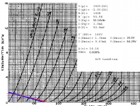
DIYAUDIO correspondent has written one of the neatest little applications for load lines/operating point -- and it's here: Triode Loadline Simulator v.2.5 (20141113 www.trioda.com)
Thanks for the replies.
Vgk was around .35V RMS (this is what I figured it would be after feedback) and Vo was just under 7V RMS.
Vgk was around .35V RMS (this is what I figured it would be after feedback) and Vo was just under 7V RMS.
That is an awesome little program from trioda.com. It is neat to move the operating point around and visually see the distortion. With a 6SN7, you can see the distortion at lower currents.
I don't think there is a way to use it for a circuit with an active load (CCS), though.
I don't think there is a way to use it for a circuit with an active load (CCS), though.
Thanks for the replies.
Vgk was around .35V RMS (this is what I figured it would be after feedback) and Vo was just under 7V RMS.
Are you really planning to run this at 7V rms out? What load did you use for the tests?
The 6SN7 has one of the lowest levels of intrinsic distortion. With a CCS anode load you will get extremely close to this. Operating currents of between 5 and 8 mA and plate voltages of around 150V will not be far away from ideal.
Cheers
Ian
Yes, with Vgk=.34V rms at max volume, and a gain of 20, that's what I'll get. I plan to follow with a 6SN7 differential pair (with CCS in tail).
The power tubes (KT90) will be biased around -62V.
With my measurements Ia=8ma and 160V on the plate, I get more distortion than at higher voltages on the plate. Maybe its not significant. It was consistent in multiple measurements.
The load I used? Oops, I forgot to include the 220K grid resistor for the next stage, so the answer is probably close to infinity ohms.
Please feel free to tell me if this is a flawed design (it works OK in LTspice 🙂 )
I am trying to figure out a good operating point for 6SN7. Morgan Jones says it is more linear at higher Ia. I tested my Tung-Sol 6SN7's with a common cathode circuit using Morgan Jones' best constant current source in the anode. I measured distortion with WinAudioMLS and a good sound card. The results are in the spreadsheet.
It looks to me like linearity is more dependent on increasing Va rather than Ia. Based on these results, I would pick an Ia=6-10ma, with at least 275-300V on the anode. This seems within the safe operating region.
Does anyone with more than my limited experience have any suggestions? Is the sound different at different operating points? Can this tube handle 3W at idle?
Thanks for your input.
Finding good loadlines with 6SN7s isn't all that difficult. Plate current doesn't necessarily have anything to do with it. (attached -- the 6J5 is a singleton with characteristics like one section of a 6SN7). Triodes tend to run more linear with higher VPK, like the 6BQ7. Despite the 6BQ7 spec sheet doesn't mention audio usage at all, and the squirrelly plate characteristic (undocumented variable-u characteristic?) you can find low distortion loadlines by getting that VPK up.
As for "is the sound different", that depends on a whole bunch of other factors and circuit details.
6 -- 10mA seems a bit excessive: no need to heat 'em up that much. The 6SN7GTB, a specially hardened version with controlled heater warm-up for use as a TV vertical deflection oscillator/final, has a PD= 5.0W. The earlier versions have a lower PD= 3.5W, lack the control grid radiator "wings", and the spec sheet doesn't recommend operation with Vgk > 0V. The hardened version does, and has characteristics that extend into positive grid voltage territory. These days, a lot of surplus 6SN7s are likely to be 'GTBs since these were TV tubes. Lots left over from old technicians/TV repair shops. Do keep a look-out for the lower rated, older 6SN7s if you're gonna push 'em hard.
Attachments
Yes, with Vgk=.34V rms at max volume, and a gain of 20, that's what I'll get. I plan to follow with a 6SN7 differential pair (with CCS in tail).
The power tubes (KT90) will be biased around -62V.
With my measurements Ia=8ma and 160V on the plate, I get more distortion than at higher voltages on the plate. Maybe its not significant. It was consistent in multiple measurements.
The load I used? Oops, I forgot to include the 220K grid resistor for the next stage, so the answer is probably close to infinity ohms.
Please feel free to tell me if this is a flawed design (it works OK in LTspice 🙂 )
Ah, I had not realised this was part of a power amp. For some reason I assumed it was a preamp. There is not a great deal to be gained by minimising distortion in this stage simply because it will be vastly exceeded by the distortion in the power output stage.
Cheers
Ian
There is not a great deal to be gained by minimising distortion in this stage simply because it will be vastly exceeded by the distortion in the power output stage.
Distortion on distortion sounds really bad in my opinion. Best to avoid distortion most in the early stages, if priorities have to be made.
Distortion on distortion sounds really bad in my opinion. Best to avoid distortion most in the early stages, if priorities have to be made.
I disagree. Distortion in the power stages will be orders of magnitude greater. An improvement in an early stage form 0.1% to 0.09% will not be audible in the 3% from the power stage. Better to reduce the power stage distortion first.
Cheers
Ian
Not all distortion is equal in nastiness. If the power stage makes 3% of 2H and 3H, it's one thing.
But if there's already some harmonics present, in the power stage input, they will mix with the new harmonics, and create intermodulation products.
These distortion on distortion products, while insignificant in the total harmonic distortion measurement, will to my ears sound especially nasty.
Best of course minimize distortion in all stages, but I prefer to start at the first stages for this reason.
Not all distortion is equal in nastiness. If the power stage makes 3% of 2H and 3H, it's one thing.
But if there's already some harmonics present, in the power stage input, they will mix with the new harmonics, and create intermodulation products.
These distortion on distortion products, while insignificant in the total harmonic distortion measurement, will to my ears sound especially nasty.
Best of course minimize distortion in all stages, but I prefer to start at the first stages for this reason.
This is false logic. All non-linearities produce both harmonic and intermodulation distortion. If the output stage makes 3% harmonic distortion it will also make a large amount of intermodulation distortion, far more than the earlier stages. I agree you should attempt to minimise distortion but the output stage is where you should pay the most attention.
Cheers
Ian
For power amp input stages the main issue is noise, not distortion. Of course, you can have an input stage which distorts badly but you need to be quite careless in picking an operating point to get this (or suffer from parasitic oscillation).
For some reason which I have never quite understood, people seem to forget that distortion varies with signal level. For a Class A input stage small signals guarantee small distortion.
For some reason which I have never quite understood, people seem to forget that distortion varies with signal level. For a Class A input stage small signals guarantee small distortion.
Sometimes a certain amount of "right" distortion at pre stages can improve the overall THD by distortion cancelling.
I remeber very well one of my early SE-construction.
I built this amplifier by carefully optimizing every stage to minimum distortion.
When I finally put all stages together, I had to essentially re-adjust the 1st stage to different operating point to achieve the minimum overall THD.
At this point the first stage created some "right" sort of distortion.
It is very hard (=almost impossible) to get accurate pre-distortion (which is why it is only used when NFB is not possible e.g. narrowband RF amplifiers). Thus the likely outcome is some cancellation of low order, but more high order. Curiously, this is exactly what people complain about with NFB - but NFB has the advantage of trying to reduce anything in the output which is not in the input, whereas pre-distortion just has to guess what might be in the output.
I'm not sure that THD minimisation should be a design goal.
I'm not sure that THD minimisation should be a design goal.
It is very hard (=almost impossible) to get accurate pre-distortion (which is why it is only used when NFB is not possible e.g. narrowband RF amplifiers). Thus the likely outcome is some cancellation of low order, but more high order. Curiously, this is exactly what people complain about with NFB - but NFB has the advantage of trying to reduce anything in the output which is not in the input, whereas pre-distortion just has to guess what might be in the output.
I'm not sure that THD minimisation should be a design goal.
It's not really about pre-distortion if you mean high distortion figures but just carefully chosen devices and operative conditions. This is not easy, especially if one wants to get it over a wide frequency range where the OT makes a lot of difference as well, and not always possible but where it can be done it works for me.
The 6SN7 will work quite nicely with things like 2A3, 300B etc. At low level the 6SN7, being rather linear in a wide region of plate curves, can be set-up to have low distortion anyway. It's just the way distortion (namely and possibly the 2nd harmonic only, but unfortunately just a little of 3rd in general) increases with signal in a complementary way compared to the driven tube. The overall distortion at all levels can be a lot lower up to rated power. For example, the typical 300B SE can have 0.1% at 1W and just over 1% at 9W rather than 0.3-0.4% and 3-4%, respectively. A that point one can still apply some fb and improve but not necessarily.
The spectrum will still have dominant low order harmonics (2nd and 3rd) but in nearly equal amounts equating to much less THD opposed to widely dominant 2 nd of amps that don't use this technique. Higher harmonics will be extremely similar (just to be on the safe side....). This measures and sounds better to me, especially at mid-low frequency.
Last edited:
No. When I say "pre-distortion" I mean the engineering technique of pre-distortion: attempting to reduce output distortion by distorting the input in an inverse way. What artosalo described is pre-distortion. There are good reasons why pre-distortion is rarely used in audio.45 said:It's not really about pre-distortion if you mean high distortion figures but just carefully chosen devices and operative conditions.
If you arrange, say, 5% of second to cancel 5% of second then you almost certainly will also get 0.25% of third (combined with whatever 3rd is already present from the stages). Note that this effect happens in cascaded circuits, not in PP. I suppose that having decided (for whatever reason) to use a distorting output stage you then have to make the best of it.
Practical or not, but I want to describe one simple case where the distortion cancelling can be observed. (assuming one has distortion meter).
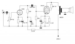
Attached is a simple SE-amplifier with triode connected TV-sweep tube 6P31S (=EL36).
The bias point and components around output tube are selected to minimum THD.
The pre stage is basic voltage amplifying stage with 6N9S (=6SL7).
If the pre stage alone (with 220k load) is adjusted to minimum THD, the cathode resistor should be 680 ohms and Ua = 130 V.
But if the whole amplifier is tuned to minimum THD by adjusting the cathode resistor of 6N9S, the optimum value will be 2k2 and Ua = 180 V.
The THD of 6N9S in latter case is more than double compared to first case with 680 ohms cathode resistor, but the THD of whole amplifier is considerably reduced.
Attachments
- Home
- Amplifiers
- Tubes / Valves
- Operating point for 6SN7