Hi there,
Looking into my drawers, I have found (some decades old) Opa124 and OP27.
Wolud they be usable (in any position) in Openamp1?
Also, having some Op07 ( for dc servo), does it make difference (again, in this posoIion) between OP177 or OPA134?
Thanks,
T.
Looking into my drawers, I have found (some decades old) Opa124 and OP27.
Wolud they be usable (in any position) in Openamp1?
Also, having some Op07 ( for dc servo), does it make difference (again, in this posoIion) between OP177 or OPA134?
Thanks,
T.
OPA124 could be used in the first position as it is a fet, but has a very low slew rate. (1 - 1,5 v/us)
DC servo op07, op177
DC servo op07, op177
Greetings all,
I have several PMA's creations, and I was wondering if by a chance anybody would have a spare PCB?
Kindest regards,
M
I have several PMA's creations, and I was wondering if by a chance anybody would have a spare PCB?
Kindest regards,
M
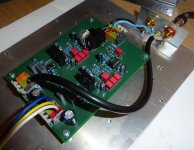
Well almost done, I was a bit scared of smd soldering but in the end it turned out pretty good. On the first position I used the excellent ADA4610-1 and the servo is in charge of the OP177GPZ. I'm just waiting for the LT1010 and it will be done.
How does it work with ADA4610-1 ?
Question:
In reference to post#60
"above 1kHz the noise in MM preamp is dominated by the 47k standardized load resistor"
Does this technique reduce the noise caused by the loading resistor? Has anyone tried this?
I use "passive cooling" 150k/25pF input instead of 47k\150pF for both lowering noise and also widening freq resp with budget MM
Detailed see here https://www.patreon.com/posts/mm-constant-loop-67857060
Just finished building Opanamp1 using pcb from craigtone. Using Jung/Didden Superreg for the PS. Will listen for a few days and post my findings.
Question:
In reference to post#60
"above 1kHz the noise in MM preamp is dominated by the 47k standardized load resistor"
The following phono preamp uses what they call "electronic termination" or "“Electronic Cooling” and according to this whitepaper it reduces the input noise by (in the limit) 13.28 dB
whitepaper:
www.akitika.com/documents/ElectronicCooling.pdf
schematic:
www.akitika.com/documents/SchematicPhonoPreampRevB4.pdf
Does this technique reduce the noise caused by the loading resistor? Has anyone tried this?
Apologies for the late reply... I use it all the time, but that 13.28 dB from the whitepaper is when you only look at the noise contribution of the termination resistor. It's more like 3 dB when you take the cartridge thermal noise into account, including iron losses. It gets even smaller when you account for other noise sources such as amplifier voltage noise and record surface noise, but then again, termination resistor noise and cartridge iron losses thermal noise mainly contribute to high frequency noise that sounds more annoying than lower frequency noise.
See also "Noise and moving-magnet cartridges", Electronics World October 2003, pages 38...43, https://worldradiohistory.com/UK/Wireless-World/00s/Electronics-World-2003-10-S-OCR.pdf Mind you, Electronics World drew one of the sections of the gain switch in the wrong state in figure 5 and I mixed up the terms spectral density and power spectral density. It's a technique from 1939, by the way.
Nick's alternative is very interesting if you don't mind building the amplifier into the turntable and if you don't have a cartridge with a strong mechanical resonance. It improves noise as well as frequency response.
The whole KIT is available here https://imrad-com-ua.translate.goog..._sl=ru&_x_tr_tl=en&_x_tr_hl=ru&_x_tr_pto=wappSo just to ask is there a shared BOM available all ready at Mouser Digikey Etc??
shouldn't discussion about another design be in its own thread?
I build this preamp just for fun on test pcb with a zener regulated linear power supply with +-12V rails, and I was blown away how good it performs. Fast, precise, good separation, good soundstage, and very transparent sound, and it sounds better than my Project DS3B...
I'm using it with a Nagaoka MP-200 MM cartridge mounted on Project RPM1.
I'm using it with a Nagaoka MP-200 MM cartridge mounted on Project RPM1.
All, thank you for your comments in this thread. I have recently created a document on MM preamp testing with respect to noise under real world conditions with a MM cartridge, a kind of comparison between measurements with low output impedance generator versus MM cartridge connected to the input. The differences are big. For those interested, below is the link.
https://pmacura.cz/MMpre_measuring_methods.pdf
https://pmacura.cz/MMpre_measuring_methods.pdf
Interesting, I didn't know ASR also measured phono preamplifier noise incorrectly, like Stereophile and Elektor and some Japanese standard.
For some reason the measured noise around 10 kHz with FET op-amp and cartridge is less than the simulated noise, while the simulation does not include iron losses. Is this close to the resonance of the cartridge with the load capacitance perhaps? Near resonance, iron losses may reduce the impedance peak.
For some reason the measured noise around 10 kHz with FET op-amp and cartridge is less than the simulated noise, while the simulation does not include iron losses. Is this close to the resonance of the cartridge with the load capacitance perhaps? Near resonance, iron losses may reduce the impedance peak.
They do, unfortunately, and when I started to explain they do it wrong I got a 2 weeks ban 😊.
BTW, I have extremely short wires from cartridge to the input terminals, as shown on the thumbnail below.

Yes, I have noticed it as well. But the resonance is higher, rather close to 20kHz.For some reason the measured noise around 10 kHz with FET op-amp and cartridge is less than the simulated noise,
BTW, I have extremely short wires from cartridge to the input terminals, as shown on the thumbnail below.

At 10 kHz, a bit less than 1.5 dB can maybe be explained with iron losses and differences in capacitance between simulation and reality.
Assuming that termination resistor losses and iron losses dominate at 10 kHz and that the iron losses can be modelled with an extra parallel 47 kohm resistor (very rough estimate), and neglecting everything else:
Measurement:
425 mH and 20 kHz resonant frequency -> 149.0017407 pF of parallel capacitance
Susceptance at 10 kHz: B = 2πfC - 1/(2πfL) ~= -28.08616643 j uS
With 47 kohm parallel resistance:
G = (1/47000) S
Effective series resistance:
R = G/(G2 + B2) ~= 17.13745109 kohm
With 23.5 kohm (that is, including guesstimated iron losses): effective series resistance 16.3690873 kohm
Simulation:
Capacitance 250 pF
Susceptance -21.74025864 j uS
With 47 kohm: effective series resistance 22.99346309 kohm
10 dB • 10log(22.993... kohm/16.369... kohm) ~= 1.475799212 dB
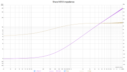
I see that the phase goes to about +80 degrees, rather than +90 degrees. The impedance of the Shure V15-III that a former colleague of mine once measured had a maximum phase of about +72 degrees.
Attempting to read off the values at 10 kHz:
23 kohm, 78 degrees
4.781968889 kohm + 22.49739482 j kohm
9.039638731 uS - 42.52815655 j uS
Equivalent to 110.6238899 kohm in parallel with 374.2342862 mH at 10 kHz.
Apparently your cartridge has considerably less iron losses than my guesstimate.
Attempting to read off the values at 10 kHz:
23 kohm, 78 degrees
4.781968889 kohm + 22.49739482 j kohm
9.039638731 uS - 42.52815655 j uS
Equivalent to 110.6238899 kohm in parallel with 374.2342862 mH at 10 kHz.
Apparently your cartridge has considerably less iron losses than my guesstimate.
Cartridge in parallel with 47 kohm and 149.0017407 pF:
30.31623448 uS - 33.16610107 j uS
effective series resistance 15.01499183 kohm
Recalculating the ESR at 10 kHz of the simulation model, now including the 970 ohm and 425 mH of the cartridge model and the 47 kohm with 250 pF:
23.03022064 kohm
10 dB • 10log(23.03022... kohm/15.0149... kohm) ~= 1.857729985 dB
A bit more difference than in post #235.
Quite remarkable SNR result of Openamp (with NE5534 op-amp) under real world system consisting of:
Technics SL-1200MK2 turntable ==> Ortofon 2Mblue cartridge ==> Openamp with NE5534 ==> 10m single ended Tasker C121 shielded cable between 2 rooms ==> measuring place in my home lab
SNR is 77.24dBA referred to 5mV/1kHz input:

Technics SL-1200MK2 turntable ==> Ortofon 2Mblue cartridge ==> Openamp with NE5534 ==> 10m single ended Tasker C121 shielded cable between 2 rooms ==> measuring place in my home lab
SNR is 77.24dBA referred to 5mV/1kHz input:

Turn on the SL-1200mk2, set it rotating, cued-up and place the cartridge over the platter...
Then bring the headshell nearer the centre of the record. Real world S/N before even hitting the record.
Cheers, John 🙂
Then bring the headshell nearer the centre of the record. Real world S/N before even hitting the record.
Cheers, John 🙂
- Home
- Source & Line
- Analogue Source
- OPENAMP1 - MM phono preamp open project
