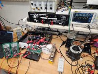
Ok, I tried larger grid stoppers and RC snubbers on the tube sockets, but no fundamental change of the osciallation. At one point I started comparing the oscillation wave-form as seen on the tube sockets and on the PCB. The tube socket showed a smooth, almost perfect sine. The PCB had more like a saw tooth, which meant the high-frequency source was on the PCB, not with the tubes. Looking at the circuit long and hard, I realised the mu resistor of the mu stage ("Gyrator") forms a local feedback loop, so I changed its value. A lower value solved the problem!
After the mu resistor was solved, I could see no osciallation even without any grid stopper at the tube socket. Should I continue without grid stoppers (for best best behaviour at positive grid voltage), or is this asking for trouble down the road?
After the mu resistor was solved, I could see no osciallation even without any grid stopper at the tube socket. Should I continue without grid stoppers (for best best behaviour at positive grid voltage), or is this asking for trouble down the road?

Looked at this again. The CCS "lower" FET in the mu-stage cascode works at about 3 V from Drain to Source and 20 mA Drain current. This operating point is not covered by the curves shown in the AOT1N60 data sheet, so I ran my own curves.AOT1N60 900mS.
Each of them datasheet shows "from-to" or defined gfs data, but all measured at ten-few ten D-S voltage.
The method of use -in this case- gives -about- 1-2V, so gfs degrading here, but generally higher datasheet value gives lower output impedance.
Turns out the characteristics of the AOT1N60 are not great around this operating point. The curves are far from flat, which means the AOT1N60 is sensitive to any change in its Drain-Source voltage due to the AC variation of the "upper" cascode FET. Transconductance is gfs = 0.12 A/V, much lower than the quoted 0.9 A/V value.
I guess the good old DN2540 part might be a better choice, because it has very flat curves down to less than 2 V Drain-Source voltage, making it insensitive to AC variations of the Vgs voltage at the "upper" cascode FET. The gfs and Crss parameters are about the same (or slightly better) than those of the AOT1N60, so no loss there.
Last edited:
This is fantastic information, thank you for sharing your measurements!
I have used a BJT in lieu of the lower FET in high voltage current sources, under the assumption that Vbe is limited by the the upper depletion mode FET's Vgs. In some cases, protection diodes might be needed for startup conditions. The benefit is that you can select for a BJT with a high early voltage and low saturation voltage, and in some cases get a more favorable combination of low capacitance and high transconductance than if you were to use only FETs. Here are some measurements that I took for current sources, I think the findings will translate well to a mu-follower's performance.
First off, a ZTX851 cascoded by a IXTP08N100D2 at 88mA. The CCS shunt capacitance is around 40pF, a bit high. The huge increase in impedance going from 9V to 18V makes me think the upper FET needs the headroom. X-axis is Hz, Y-axis is ohms.


Here's what I got with the DN2540 and IXTP08N100D2 (don't mind the typo in the graph) at 22mA-- a bit closer to your op point-- in a traditional 2-terminal CCS. The shunt capacitance seems to be around 12pF. While the results are comparable, this CCS is running at a quarter of the current of the BJT implementation. I'd expect the BJT to trounce the DN2540 at 20mA, but would select a lower capacitance part. The KSC3503 has both a high Va and low capacitance, and would probably be my go-to. BC337 measures a bit worse than the ZTX851.

Ale likes the BSH111BK as well, and I think its performance is in the same ballpark as that of the BJTs. I only tested it around 81mA, and ultimately went with the BJT in my circuit. Shunt capacitance is around 30pF with a DN2540 on top (which means a smaller voltage drop across the FET than across the BJTs above). I used a lower value degeneration resistor than in the BJT circuits to make up for the BSH111BK's 1V Vgs as compared to the 500mV Vbe of the BJTs.

I have used a BJT in lieu of the lower FET in high voltage current sources, under the assumption that Vbe is limited by the the upper depletion mode FET's Vgs. In some cases, protection diodes might be needed for startup conditions. The benefit is that you can select for a BJT with a high early voltage and low saturation voltage, and in some cases get a more favorable combination of low capacitance and high transconductance than if you were to use only FETs. Here are some measurements that I took for current sources, I think the findings will translate well to a mu-follower's performance.
First off, a ZTX851 cascoded by a IXTP08N100D2 at 88mA. The CCS shunt capacitance is around 40pF, a bit high. The huge increase in impedance going from 9V to 18V makes me think the upper FET needs the headroom. X-axis is Hz, Y-axis is ohms.
Here's what I got with the DN2540 and IXTP08N100D2 (don't mind the typo in the graph) at 22mA-- a bit closer to your op point-- in a traditional 2-terminal CCS. The shunt capacitance seems to be around 12pF. While the results are comparable, this CCS is running at a quarter of the current of the BJT implementation. I'd expect the BJT to trounce the DN2540 at 20mA, but would select a lower capacitance part. The KSC3503 has both a high Va and low capacitance, and would probably be my go-to. BC337 measures a bit worse than the ZTX851.
Ale likes the BSH111BK as well, and I think its performance is in the same ballpark as that of the BJTs. I only tested it around 81mA, and ultimately went with the BJT in my circuit. Shunt capacitance is around 30pF with a DN2540 on top (which means a smaller voltage drop across the FET than across the BJTs above). I used a lower value degeneration resistor than in the BJT circuits to make up for the BSH111BK's 1V Vgs as compared to the 500mV Vbe of the BJTs.
Bad weather, winter is coming. Time to switch from outdoors mode to the workshop.
The last tests from a few months back showed boring behaviour with some KT66 dummies for the output tubes (no magic smoke, no big bangs, no silicone shards). So I went on and put the DHT outputs back there. Works fine! It looks like the change the AOT1N60 to the DN2540 parts in the mu-stage was indeed a good idea to make things stable.
Frequency response (-3 dB, no load) was 7 Hz to 180 kHz. AC output went up to about 1.6 kVpp before clipping.
I'll need to rebuild the 580 V bias before I can listen to it with a headphone.
Attachments
Last edited:
Wishing everyone a good start and a great DIY time in 2025... 🙂

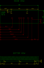
What's the best way to drill and tap clean holes in heatsinks? I've got some 300 x 40 x 100 mm heatsinks for the OSDEHA, and I need to mount the transistors and chassis panels to it. M3 and M4 threads, see attached diagram. I have done this stuff before, but I am not good at it. Lost more than one broken tap in a heatsink... Any hints?
Attachments
just stumbling on this thread - really good read to see the theory and evolution of the ideas.
tapping - slow and steady , use cutting fluid, do it by hand - a few millimeters forward, then back out and inch the cutting edge forward - repeat until you get to the required depth. If others have better guidance, i am all ears too.
..dB
tapping - slow and steady , use cutting fluid, do it by hand - a few millimeters forward, then back out and inch the cutting edge forward - repeat until you get to the required depth. If others have better guidance, i am all ears too.
..dB
Best way is not to bother.What's the best way to drill and tap clean holes in heatsinks?...
I use L extrusion clamp(s), 1 screw every other transistor.
The pressure is evenly distributed, you can afford to tighten somewhat more then the nominal 0.6-0.8 N.m of torque, and, most of all, no precision drilling and tapping required!
Last edited:
The bracket will surely work, but some tapping is still needed. It's just something I don't enjoy doing.
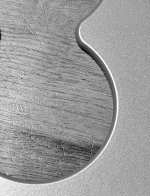
First heatsink is done, no hickups. With the second heatsink, the drill bit came out on the back, but only half way. The other half was caught in one of the cooling fins, and decided to break off in there. That resulted in a twisting of the whole heatsink, so the drill bit also broke on the front side. The middle piece is stuck in the heatsink for good... I can braze a bike frame, lace wheels/spokes, and make beautiful bikes -- but simple tapping of heatsinks goes wrong everytime! 😡
First heatsink is done, no hickups. With the second heatsink, the drill bit came out on the back, but only half way. The other half was caught in one of the cooling fins, and decided to break off in there. That resulted in a twisting of the whole heatsink, so the drill bit also broke on the front side. The middle piece is stuck in the heatsink for good... I can braze a bike frame, lace wheels/spokes, and make beautiful bikes -- but simple tapping of heatsinks goes wrong everytime! 😡
Another trade secret of mine: since I'm too old & lazy to learn yet another CAD, I use PowerPoint for all my chassis works:
- Choose a suitable initial scaling factor, like 1:1
- Choose a suitable "paper" size, like A4
- Draw a rectangle, 25x15cm with PowerPoint's measuring system
- Measure the actual dimensions
- Calculate the actual scaling factor
- Apply this to your drawing either by scaling, or, more conveniently, with the scaling of the printer driver (1%)
- Tape the printout to the object, punch and drill
- I've been able to achieve a precision of about 0.1mm consistently.
For me, a simple 2D CAD program is easier than PowerPoint. Never used PowerPoint in my life, not even at work (yes, most colleagues think I'm either a unicorn or an idiot. Or both.). I prefer simple software tools that do one thing at a time, and do this well.
Now comes the hardest part: waiting for delivery of FrontPanelExpress parts. Building new amp boards in the meantime. Once the chassis parts are here, I will figure out that I screwed up the design and that parts are missing. Good times ahead! 🙂
Now comes the hardest part: waiting for delivery of FrontPanelExpress parts. Building new amp boards in the meantime. Once the chassis parts are here, I will figure out that I screwed up the design and that parts are missing. Good times ahead! 🙂
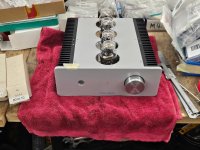
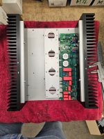
Dry fitting.
Yes, I drilled and tapped all the mount holes for the transistors on the heatsink in the positions. Feel free to rub it in... 🙄
Yes, I drilled and tapped all the mount holes for the transistors on the heatsink in the positions. Feel free to rub it in... 🙄
Attachments

cool stuffDry fitting.
Yes, I drilled and tapped all the mount holes for the transistors on the heatsink in the positions. Feel free to rub it in... 🙄
why don't you make a thread on head-fi like that?)
by the way, for some reason registration doesn't work on head-case anymore(
Head-Fi is not where the DIY guys are. It's not a place like diyAudio where people like to share their knowledge and discuss technical questions in detail.
yes, I agreeHead-Fi is not where the DIY guys are. It's not a place like diyAudio where people like to share their knowledge and discuss technical questions in detail.
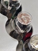
how is your amplifier?)
I see some cool tubes in it
It is under construction.😎how is your amplifier?
- Home
- Amplifiers
- Headphone Systems
- Open Source DHT Estat Headphone Amp -- OSDEHA