I'm currently working on a high-power amplifier and I'm exploring different input stage designs. I'd love to get your insights on the performance and sonic characteristics of op-amp based input stages versus discrete transistor-based input stages.
I would greatly appreciate it if you could share your experiences and attach one best input stage schematic for each category that you believe excels in performance.
Looking forward to your valuable inputs!
I would greatly appreciate it if you could share your experiences and attach one best input stage schematic for each category that you believe excels in performance.
Looking forward to your valuable inputs!
I use op amp input stages on all The Big Ones. Multiple reasons. You dont need to match the input pairs. They do it for you. Input stages only have 15 volts on them, which can be important during fault conditions. Fried input stages never expose the user to 150 volts, and the frying stops there and doesn’t typically propagate - protecting stages that follow. The amp that follows it can (and should) use local feedback, which can satisfy its own DC conditions and helps stabilize the overall loop.

~2000w rms @4ohm with .01% THDHow high power are you aiming for?
can u attach some of your schematic for reference ?I use op amp input stages on all The Big Ones. Multiple reasons. You dont need to match the input pairs. They do it for you. Input stages only have 15 volts on them, which can be important during fault conditions. Fried input stages never expose the user to 150 volts, and the frying stops there and doesn’t typically propagate - protecting stages that follow. The amp that follows it can (and should) use local feedback, which can satisfy its own DC conditions and helps stabilize the overall loop.
With the power rail voltages involved it would be easier to use transistor frontend.~2000w rms @4ohm with .01% THD
But there is countless examples of opamp circuits driving high power amplifiers.
The bigger issue is soft start circuits, DC protection relays and a power supply
That even produces that much power. Not included forced air cooling / fan controls.
All of those mandatory for such high power levels, and if the application being used even remotely comes
close to needing that much power. Not a simple design.
And likely dont need that much power.
Check out Crest Audio PRO9200 schematic maybe...
Or the PRO8200, or CA series, which is closer to what I use. I really don’t like common emitter output stages at these levels because they are harder to stabilize. One misstep at these voltages and BOOM. Big Badda BOOM. The CE stage has much lower component count, but you are more likely to lose it during development. How good are your models? Ones provided by the vendors are often worth what you paid for them. You really don’t want to make an oscillator with 320 volts between the rails. Unless it’s made with tubes.
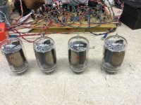
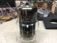
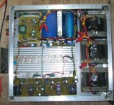
This was the test bed for the protection circuit array to be used on the next iteration of The Big One. The 2 channel amplifier itself is pretty much the same as the one in the Big One with only 2 pair of outputs and just a regular +/-52V rail. It is easily recognizable if you know what to look for and use a minuscule amount of the space. And this photo doesn’t even show the fan/relay power supply driver board which is separate. Like I say, these circuits must be fully vetted before you begin. You can see more complete versions behind the tubes. It as done on a perfboard so I could jack with it till things were working the way I wanted them to. I jacked with it on and off over a YEAR before I ever started the new PCB layouts for the big ones.
Attachments


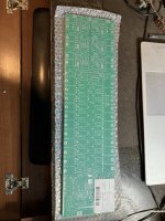
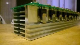
The PCB proof for the big one. It’s just a proof with 1 ounce copper, to be reordered in 2 ounce after any corrections. I already used it to drill the heat sinks for 7 units (! Using the mounting holes, which will be truncated on the reorder so I can get to the screws). The two 12 pin connectors go to the daughterboard which contains all the supervisor circuitry. You can clearly make out the supply commutators, transistor banks, and the rest of the audio - which is tiny.
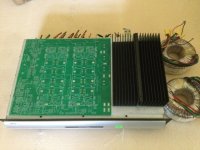
The other is a single board 600 W/ch class H similar in principle to the Apex H900 with my front end and the QSC rail switches. That entire section to the left is protection circuitry. All of it based on what I did on that perfboard above. These are for the TWEETERS and monitor wedges. I’ve got transformers and cases, as well as drilled heat sinks for a half dozen).
When I finish building the new house everything should stay working for a couple years before it becomes one thing after another requiring constant attention like my old one did. See “The ultimate non-audio build thread” to see what’s going on there. All of this is next up in the queue when I can get all the household goods out of the SHOP. And I retire early next month, so that will help.
Attachments
I didn't prefer CE output stages, even it has many advantages. I always built emitter follower output, but not as high power. Here is biggest class AB amp i ever made (20 years ago), 600W/4ohms.Or the PRO8200, or CA series, which is closer to what I use. I really don’t like common emitter output stages at these levels because they are harder to stabilize. One misstep at these voltages and BOOM. Big Badda BOOM. The CE stage has much lower component count, but you are more likely to lose it during development. How good are your models? Ones provided by the vendors are often worth what you paid for them. You really don’t want to make an oscillator with 320 volts between the rails. Unless it’s made with tubes.
Attachments
This was MORE than 20 years ago - I have two 1200W/2 ohm monoblocks and one 600x 2 stereo version. All that same front end using the LF412 op amp. These has to use cascode output stages since they were class AB. The current consumption at war volume was between the ridiculous and the sublime.
Attachments
its looks complicatedCheck out Crest Audio PRO9200 schematic maybe...
so what should I do ?Or the PRO8200, or CA series, which is closer to what I use. I really don’t like common emitter output stages at these levels because they are harder to stabilize. One misstep at these voltages and BOOM. Big Badda BOOM. The CE stage has much lower component count, but you are more likely to lose it during development. How good are your models? Ones provided by the vendors are often worth what you paid for them. You really don’t want to make an oscillator with 320 volts between the rails. Unless it’s made with tubes.
Be patient and learn. NO ONE should build amplifiers of this magnitude until they already know how to build amplifiers. Large basic ones, at least. You do NOT start here.
Not to mention the scary caps needed for a job like this. 300-400V and probably in the neighborhood of 100mF will toss you across the room if you’re not careful. Scary, scary stuff!
16,5000 uF. Twelve 22,000 uF in series-parallel, with each voltage tier getting 66,000 uF at about 40V. The “right” amount of capacitor is about 20,000 uF for a 2 channel low-ohm capable amplifier. Regardless of size. It’s about the pole frequency due to the load impedance. Look at it as it were a coupling cap, and size the cap accordingly. Then you get good low frequency behavior down to that frequency.
You really don’t want to make the power factor any worse by using stupid amounts of cap. When the pole frequency is in the single digit Hz enough is enough. It will vaporize screwdrivers or your good Klein diagonal cutters….
If a three-phase supply is available, the bus capacitance (for the same ripple) could be significantly reduced while keeping the PF intact. I am writing this only because the desired power is in the thousands of watts.
The ripple for a 3-phase FW rectifier without any capacitor is only around 4%.

The ripple for a 3-phase FW rectifier without any capacitor is only around 4%.
- Home
- Amplifiers
- Solid State
- Opamp vs discrete transistor based input stage for High power amp , your thoughts ?