I couldn't find anything about this technique in some quick searches, so I thought I'd present my version.

Typical high performance opamps are limited to 36V supply range or thereabouts. This is fine for a power amp with +/-18V rails, in which an opamp can provide IS and VAS in one with good performance at low cost.
For more powerful amps the rail voltages can be +/-35..70V or more, which suggests an opamp is unable to take on the role of the VAS, and designs exist using an opamp as just the IS.
However opamps can be stacked in a pyramid formation, each tier bootstrapping the supplies of the next, allowing the synthesis of a composite amplifier with +/-36V, +/-54V, +/-72V rails etc.
The constraint is that the gain is fixed at N where N is the number of tiers. Adding an extra opamp at the input for more gain is thus needed. A zener stack is needed to replicate the input vertically for the pyramid.
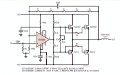
My example uses a 3-tier stack, driving a simple bipolar OS.
I picked one of the many opamp models in LTspice that seemed to emulate less slowly that some (I'd really like a rail-to-rail high performance opamp model).
It seemed to emulate OK without decoupling caps (which would complicate the stack somewhat).
I wonder what the practical reality is for such a topology though. Clearly you want the opamp to have full 36V range or better, low quiescent current (since one opamp has to power several others), high output current ability, and you are limited to single opamps as each device has different power rails. Cheapness is clearly an advantage.
So does this actually work?
Typical high performance opamps are limited to 36V supply range or thereabouts. This is fine for a power amp with +/-18V rails, in which an opamp can provide IS and VAS in one with good performance at low cost.
For more powerful amps the rail voltages can be +/-35..70V or more, which suggests an opamp is unable to take on the role of the VAS, and designs exist using an opamp as just the IS.
However opamps can be stacked in a pyramid formation, each tier bootstrapping the supplies of the next, allowing the synthesis of a composite amplifier with +/-36V, +/-54V, +/-72V rails etc.
The constraint is that the gain is fixed at N where N is the number of tiers. Adding an extra opamp at the input for more gain is thus needed. A zener stack is needed to replicate the input vertically for the pyramid.
My example uses a 3-tier stack, driving a simple bipolar OS.
I picked one of the many opamp models in LTspice that seemed to emulate less slowly that some (I'd really like a rail-to-rail high performance opamp model).
It seemed to emulate OK without decoupling caps (which would complicate the stack somewhat).
I wonder what the practical reality is for such a topology though. Clearly you want the opamp to have full 36V range or better, low quiescent current (since one opamp has to power several others), high output current ability, and you are limited to single opamps as each device has different power rails. Cheapness is clearly an advantage.
So does this actually work?
Attachments
Last edited:

BUILD!!!
100 points for unique approach!
Never seen such... eehh... what...
And the simu says: ok.
100 points for unique approach!
Never seen such... eehh... what...
And the simu says: ok.
I have seen (and used) single layer bootstrap schemes (U4, U5, U6 in your circuit) with many variations, but not stackings of higher order like yours.
I think there are first-order examples on this site: IIRC, member jcx is fond of such topologies, but the purpose is mainly directed at linearity improvement, not especially voltage swing, but killing two birds with one stone is certainly an advantage.
Your scheme seems to have an advantage in terms of gain definition and common mode handling, which is an added bonus.
I have to analyze the circuit more thoroughly, but at first sight, I do not see what U2 is for? (except perhaps for current drive considerations?)
I have myself contemplated > first-order bootstraps, but I thought at the time that this was not worth pursuing, one of the reasons being that you need to use single opamp packages.
I faintly remember that in the late 70's or early eighties, Wireless World ran a series of articles on a related subject: floating-bridge amplifiers, but I do not remember how the stacking was organized.
I certainly have the articles somewhere in my paper archives, but nowadays it is probably simpler to search on American Radio History
It is a clever circuit anyway, bravo!
The topology is a little clearer drawn this way:

And this halves the number of zeners as the resistor dividers are in the second tier.
And of course the principle applies to power amplifiers too, although I think not economically (except perhaps for
jelly-bean chip amps).
And this halves the number of zeners as the resistor dividers are in the second tier.
And of course the principle applies to power amplifiers too, although I think not economically (except perhaps for
jelly-bean chip amps).
Last edited:
Hi Mark,
Nice idea😎
Thread Surjan Dogran's Easy Peasy 70v peak-peak Opamp for $1 and
EDN May 13, 1999 https://m.eet.com/media/1152270/24127-45890.pdf
The TLC6090 is +/-70V with about 10mA drive https://www.analog.com/media/en/technical-documentation/data-sheets/6090fe.pdf
One application in there is for LatFets on p21 (attached).
Maybe the TLC6090 can also be stacked like your circuit for +/-100V ...
BTW Floating bridge is by Brady, Wireless World, Sep 1980 and Oct 1980.
Attachments
The topology is a little clearer drawn this way:
And this halves the number of zeners as the resistor dividers are in the second tier.
And of course the principle applies to power amplifiers too, although I think not economically (except perhaps for
jelly-bean chip amps).
Very cool nice appoach!🙂
Hi Mark,
Nice idea😎
Thread Surjan Dogran's Easy Peasy 70v peak-peak Opamp for $1 and
EDN May 13, 1999 https://m.eet.com/media/1152270/24127-45890.pdf
The TLC6090 is +/-70V with about 10mA drive https://www.analog.com/media/en/technical-documentation/data-sheets/6090fe.pdf
One application in there is for LatFets on p21 (attached).
Maybe the TLC6090 can also be stacked like your circuit for +/-100V ...
BTW Floating bridge is by Brady, Wireless World, Sep 1980 and Oct 1980.
Hmm, that transistor circuit rather finesses the problem! Oh well.
[ edit: Ah, not quite, its still limited to a x2 gain for max swing as one opamp input is tied to ground, in fact it will burn the opamp if over driven, the non-inverting input needs protection. For greater than x2 swing I think the transistor approach can be stacked, but is limited in gain in the same way - the opamp approach keeps all the voltages better controlled which matters for stacking. ]
Last edited:
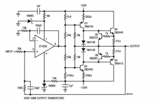
I've realized the transistor bootstrapping circuit of Surjan Dogran's can go up to a tripling of output voltage swing if the gain is set to 3, non-inverting. This version uses 50V rails, runs an opamp at +/-18V (limited by a zener for protection) and has the bootstrapping split into a DC and AC path to allow the bootstrap factor to set optimally even though the rail voltage isn't 3 times 18V.

Of course an input opamp is needed if a gain more than 3 is wanted, but the output swing is about 90V p2p.

Note the opamp's rails swing well above and below ground as they track the output, but the input voltages should just stay within limits - a protection resistor and clamps on the non-inverting input would be a wise precaution.
This circuit could drive a similar circuit using the LTC6090 to triple the swing again (LTC6090 swing is 140V), so upto 270V swing would be possible.
Last edited:
Well, in the end, there seems to be a consensus on the practicality and convenience of bootstrapped rails:I've realized the transistor bootstrapping circuit of Surjan Dogran's can go up to a tripling of output voltage swing if the gain is set to 3, non-inverting. This version uses 50V rails, runs an opamp at +/-18V (limited by a zener for protection) and has the bootstrapping split into a DC and AC path to allow the bootstrap factor to set optimally even though the rail voltage isn't 3 times 18V.
EZ-Dump: dump your current without really trying
But of course, this does not detract from the merit due to the pyramidal scheme, which is compatible with the bootstrap, in case the swing available is not sufficient.
I happily welcome any new and creative approach, and the pyramid certainly counts as such
hows the performance, especially when clipping


Seems OK, if the emulation is good. I added 1k input resistor to the non-inverting input. In practice it won't clip much as the opamp driving it will clip anyway.
I happily welcome any new and creative approach, and the pyramid certainly counts as such
Thanks, it was quite pleasing to figure it out - actual breadboarding it might not happen for a while as I mainly have SMT dual opamps at hand...
[ The tripler circuit may get breadboarded soon, though, I have a +/-48V supply. ]
I built some systems using Doug Self's Class G topology which has similarities. I never could get it to sound better than his blameless class B. So forgive me if I smell a free lunch here.
I'd check a few things before building.
PSRR - what does output look like if you put 1uV signal into either supply line.
real load - what happens if you add a bit of parallel C or series L in that 2K load resistors.
Op-amp supply voltage - in-circuit, worst case load, related to PSRR but any datasheet violations?
there's a lot of complexity with this solution so expect unforeseen interactions.
Opamp circuits aren't very sensitive to rail noise, I sometimes test simulations by injecting 1V tones into the rails and see how much they bleed into the output or intermodulate the output.
BTW are you talking about the pyramid driving an OS - I presume so due to the complex load question - I'm not advocating any particular OS, that's just the motivation for the topology.
The tripler is just part of a VAS stage so its load would be the drivers or pre-drivers.
And I've tested the tripler using +/-45V rails and an LT1113 I had knocking about. Seems to work stably and was getting 80V p2p out into 10k load. I used KSA992/KSC1845's as the bootstrap transistors so they were running a little hot, didn't want to drive a heavy load.
I realized the zener that protects the opamp from over-voltage can lead to heavy current draw through the transistors if the biasing network isn't setup correctly for the supply voltage - it might need a bit of rethinking.
Last edited:
Yes, driving an OS as in your schematics above, in turn driving a real speaker with challenging crossover.
Good point about the bootstrap transistors, they're dissipating almost 0.5W each quiescent. Driving the drivers will increase this dissipation.
Is there any way the V+ supply to op-amp could be less than the in/out voltage (vice versa for V- rail)?
A square wave test would be revealing.
There's so much more to consider with a complex design like this and I can't convince myself on first view that this is unconditionally stable. Personally, I've lost many battles to a simple cascode VAS as demonstrated by Self et al. so I appreciate what you're trying to do here.
sorry to drag the meal metaphor along, but the proof of the pudding....
Look forward to hearing more.
🙂
Is there any way the V+ supply to op-amp could be less than the in/out voltage (vice versa for V- rail)?
Attachments
- Home
- Amplifiers
- Solid State
- Opamp pyramid stacking for higher voltage operation