Does the 552 manage without an input bias current source?
Why have you turned the output stage and the supplies upside down?
Why have you turned the output stage and the supplies upside down?
Not sure it might.... I dont know anything about that... Gona smoke?
I swaped them once... Then took my medicine and swaped them again...
I quitted smoking 3 weeks ago and i still can not concentrate...
Got myocarditis and alot slower blood circulation, my brains sucks oxygen like a freakin bugatti veyron W16...
Ill swap them again...
windows print screen
I swaped them once... Then took my medicine and swaped them again...
I quitted smoking 3 weeks ago and i still can not concentrate...
Got myocarditis and alot slower blood circulation, my brains sucks oxygen like a freakin bugatti veyron W16...
Ill swap them again...
An externally hosted image should be here but it was not working when we last tested it.
windows print screen
Last edited:
You've got this all the wrong way around.
First of all you need the feedback to come from the main output to the speaker.
Then your drivers should be working in Class A ideally and the emitters of the drivers go to the bases of the power transistors and the resistors go to the opposite rail. Those eBetween the two bases of the drivers you need 4 diodes to keep them apart or a Vbe multiplier. NPNs at the top and PNPs at the bottom.
If you're running it from just +24V then you'll need set a bias voltage of 12V or thereabouts. Is this a dual supply or a single? I find it nearly impossible to find my way around this. Put V+ at the top and V- at the bottom and then we might more easily see what's going on.
I don't know what the two caps are doing, whatever the case you only need 1. But even then you want the bias voltage to be there at the output. If you are running from a single supply then you'll need a big cap on the output. Nor do I know what the Rs are doing. If that's meant to be setting Iq, then that's not how you do it. All that seems to be doing is plonking whatever is on the power rails onto the signal.
It seems to be just miles away, I'm sorry to say. Wait for Gerald to post his schematic.
I suggest you download a copy of LTspice (free) and go to Cordellaudio.com and download his examples from the tutorial section - or better still buy his book, along with a copy of the Art of Electronics.
This was the last one I saw, and it's about as good as they get.
http://www.linearaudio.nl/linearaudio.nl/images/pdf/otala low tim amp.pdf
Go to page 15, where you'll see the schematic. Your part really begins at T12 and T15. (Basically you need most of what's to the right.) He's using T11 to keep them apart. You could do that, or you could ignore it or you could use diodes. Ignore the fact that he has paralleled up two sets of output transistors.
Here's a better one to look at. This is the whole thing. Of course Rod Elliot has got there before everyone. Again.
Opamp Based Power Amp
Really, just copy that.
Opamp Based Power Amp
Really, just copy that.
Damn, scratch that. He's got CFPs on the output. Great idea but you have to be careful. But that's the sort of model. Blend the two if you can.
Well, I truly got lost after i took those "chillpills" Probably im never going to take them again.
I hope this SCH is something similar to what I am trying to get
pictures upload
I hope this SCH is something similar to what I am trying to get
An externally hosted image should be here but it was not working when we last tested it.
pictures upload
That's getting closer, and might even work. That's not quite how I'd like to do a CFP, but that may be the only way if that's how the bias is going.
Let's be clear. Just using your two power transistors, npn at the top and pnp below, by themselves and with nothing else, will work. There's probably enough beta to do it with those trannys. What happens there is that the crossover distortion gets corrected by the op amp.
When we get to adding drivers, you lighten the load on the op amp and you can get adjust the bias, and with it the quiescent current. You can't get this adjustment so easily with diodes, though they do work perfectly well. If you want to push this amp well into Class A then this adjustment is probably needed, but you are going to need a big heatsink. And I mean really properly big. They'll be dissipating 60W perhaps and even with TO-3s it might be worth pairing up output trannys. Class AB, and even some way towards Class A will be fine, but with 2A of standing current you are moving towards the Krell ideals and you'll need a pretty good power supply with a lot of capacitance.
Whatever happened to the 10W idea? Because at +-28V you are embarking on the ambitious. Getting 30W from a Class A amp is quite an endeavour.
What impedance are your speakers?
If I can get a bit of time to get into the PC part of this laptop then I'll knock up something that ought to work.
Personally, what I would do in your position is get a couple of PP3s. Hook them together to give you +-9V and just lash up on a bit of stripboard any op amp with two power transistors, but each with emitter resistors of perhaps 0.33 or 0.47 (whatever you have to hand). Make sure you bypass the op amp with a couple of 100nf to 2u2 capacitors. Give it a gain of 15-20 and see how it works.
I have a power supply with 44K uF per rail... I can triple that...
I got 2 250VA toroid transformers with dual 20 secondary.
The capacitors are made by SAMWHA and are the cheap ones...
The power supply might cost more than 100€..
I got 2 1,C°/W but i think Id need a lot bigger heatsinks...
Shown on the picture, Chipamps inside, I dont like them anymore.
screenshot windows 7
But theres a problem... I ordered handful of transistors...8of Those MJ1500.. 4 sets of drivers incase i mess something up...
I also had to ask TI for free samples, as i want to try all possible HV opamps they have..
Even motor drive ones 😀
Theres something really cool... T shaped (THICK) aluminium bars I mean like 5+mm in thickness i got from vintage amp that had KT808s as outputs. Russian version of QUAD-405 ..
picture uploading
The problem with Class A would be mains noise if i use those transformers... SMPSU would be perfect but yeah...
I got 2 250VA toroid transformers with dual 20 secondary.
The capacitors are made by SAMWHA and are the cheap ones...
The power supply might cost more than 100€..
I got 2 1,C°/W but i think Id need a lot bigger heatsinks...
Shown on the picture, Chipamps inside, I dont like them anymore.
An externally hosted image should be here but it was not working when we last tested it.
screenshot windows 7
But theres a problem... I ordered handful of transistors...8of Those MJ1500.. 4 sets of drivers incase i mess something up...
I also had to ask TI for free samples, as i want to try all possible HV opamps they have..
Even motor drive ones 😀
Theres something really cool... T shaped (THICK) aluminium bars I mean like 5+mm in thickness i got from vintage amp that had KT808s as outputs. Russian version of QUAD-405 ..
An externally hosted image should be here but it was not working when we last tested it.
picture uploading
The problem with Class A would be mains noise if i use those transformers... SMPSU would be perfect but yeah...
Last edited:
I like the Aluminium thingie, but if you want Class A then two of those - and cover the back of each with a fat and deep heatsink! That will be barely enough for a 10W amp.
Those transformers are probably just about OK. Have you got 4 bridge rectifiers? That'll wipe off a couple of volts. And I'd get prepared for making a regulator, or at least a cap multiplier (horrible things).
Nothing wrong with Samwha caps.
Those transformers are probably just about OK. Have you got 4 bridge rectifiers? That'll wipe off a couple of volts. And I'd get prepared for making a regulator, or at least a cap multiplier (horrible things).
Nothing wrong with Samwha caps.
I will go to my school workshop one day and mill ones out of copper.. ( If I can )
I will make the transistors base a lot thicker 15mm at least
Regulator? what regulator? Tell me about it 🙂
I will make the transistors base a lot thicker 15mm at least
Regulator? what regulator? Tell me about it 🙂
If you are drawing perhaps 2A in standing current (rather than a more usual 100mA or thereabouts) then the ripple on the rails is going to be a lot larger because the capacitors will discharge much more. Like 20x more! One solution to this is to regulate the voltages. In this instance it also has the advantage of wiping off another 3 or 4 volts, and bringing the supply down to a more manageable level.
I've drawn up what i think would be a good circuit but I'm having a bit of a problem over not letting all of the supply rail onto the signal path. What I have isn't working first time, as I thought it would.
I'm afraid you'll have to bear with me for a bit as it needs a bit of proper thinking and can't give it all the attention it needs right this minute. Unfortunately it's getting to look more and more like a power amp rather than a stripped down solution. I'll try to get back to it some time tonight - but it is a Friday!
I suppose that if it were easy, then someone else would have got there long ago.
I'm still not happy with R13 and R14 as a solution, but you may as well look at the circuit as it is at the moment. Anyway, there's plenty of gain in the op amp to get rid of whatever comes down from the rails.
R1 is where you vary the standing current. As set it is matched for the Vbe drops (not necessarily for crossover distortion (or probably not). Move it up to 4k7 and you'll see the current rocket to over an Amp and 30W dissipated in each transistor. I would be far happier not just paralleling these up but also having 0R47 on the emitters.
The take off for the feedback should be after the RC to Gnd (Boucherot cell) and it may well need the L//R as the rest of the zobel network. I think one could do worse, but it's not as simple as I had hoped. But if you want the flexibility of moving from Class AB to Class A, I expect this is as simple as it gets.
It's very tempting to use the LME47810, or whatever is its number, as that solves the R13/14 problem directly - and I presume doesn't just have 10k resistors from the rails. It has fantastic figures. One could get rid of R13 if you rejig it, but I don't know what that does for DC offset. This appears to be pretty good without a C to Gnd in the feedback arm.
Last edited:
No picture it seems.
Try again.
Try again.
An externally hosted image should be here but it was not working when we last tested it.
Pretty shitty quality.
If you have probs with values just ask. They can just about be deciphered. It gives you the idea anyway.
If you have probs with values just ask. They can just about be deciphered. It gives you the idea anyway.
Let's see if this is better quality.
Ignore the R1 Value of 6.8k. That was an experiment to see how far it went up! 4Amps is the answer - so, if you want to heat your room ...
It's missing a capacitor between the bases. Don't know what value to put in there yet.
An externally hosted image should be here but it was not working when we last tested it.
Ignore the R1 Value of 6.8k. That was an experiment to see how far it went up! 4Amps is the answer - so, if you want to heat your room ...
It's missing a capacitor between the bases. Don't know what value to put in there yet.
Last edited:
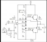
Here is the schematic of my version of a Current Boosted Opamp power amplifier circuit that I couldn't upload the other day. 🙂
I did try offset feeding the diodes from the center and I don't recall any major differences in performance but I will investigate this more when I rebuild it and work with it some more.
But you do need the diodes in order to minimize the crossover distortions.
This is something that has been failed to be recognized in the other thread using the TDA729x designs as a driver opamp.
The 1N914 or 1N4148's are fine providing you don't exceed their current ratings, else any common diode will suffice as it is only used to keep the voltage the on the base of the transistor high enough to keep them in conduction mode.
The 40% bias setting is not the true value it was just the default setting of the schematic editor in Circuitmaker2000.
As I had mentioned I don't remember why I had the .01uf capacitor in there.
I thought that I used a 100pf across the + and - inputs of the opamp to damp the parasitic oscillations and it may have been just left over when I was switching the configuration between singe ended and Bipolar supply modes.
Enjoy!!
jer 🙂
P.S. Christian I don't see your images!! 🙁
Attachments
Last edited:
- Status
- Not open for further replies.
- Home
- Amplifiers
- Chip Amps
- opamp plus driver stage and output stage with its own supply, what could happen?