Yeah to have pinouts for smaller transistor packages.I think he’s talking about the PCB layout.
CAD files and SPICE files can be found here: https://github.com/prydin/diamond-buffer-amp
I haven't generated any Gerber files yet, as I want to check it a few more times first.
I haven't generated any Gerber files yet, as I want to check it a few more times first.

It should sound okay.
But for more than headphones (low power) you normally need more current gain, so 2EF minimum. You'll see diodes used to make up the extra drop needed by the output stage.
But for more than headphones (low power) you normally need more current gain, so 2EF minimum. You'll see diodes used to make up the extra drop needed by the output stage.
Simulation and preliminary breadboard tests indicate that it drives a speaker just fine at least up to 25W. Not sure I would go higher.
I've built them before.
But that's okay. I didn't need the high OLG of an op amp to achieve low distortion. I was thinking this version would be much improved using an op amp front end. I may revisit my design later on and try to use an op amp.
But that's okay. I didn't need the high OLG of an op amp to achieve low distortion. I was thinking this version would be much improved using an op amp front end. I may revisit my design later on and try to use an op amp.
I don’t expect it to be amazing, but I like the simplicity and I’m hopeful it will be good enough for casual listening. It may take the place as a patio amplifier, replacing the rather horrific designed from scratch Class D I built as an experiment.
It should be ... those expectations are low enough so almost anything would do.
Performance can be extremely high with this type of output stage. Let 're rip, let's see how it sounds in this format.
Performance can be extremely high with this type of output stage. Let 're rip, let's see how it sounds in this format.
They are both current amplification stages, no VAS in sight, that's the opamp's job. The drivers are lower dissipation. I think the point is for thermal stability you want some sort of guaranteed relationship between the Vbe's of the two stages, which is easiest to do with matching devices.Hi No ideas,
I am missing what you are getting at. Those two are vastly different transistors, nowhere even close. One is a driver or Vas, the other an output or driver for a high current output stage.
Hi Mark,
I have designed and built more than a couple. I am aware. Thanks.
My previous comments cover the subject.
I have designed and built more than a couple. I am aware. Thanks.
My previous comments cover the subject.
By bootstrapping you mean tying the collectors to the emitters of the output transistors? Like so?
View attachment 1442588
No need for resistors R2/R3
Q1 and Q2 are folded drivers. Unlike emitter follower the current of Q1 and Q2 is very small. the actual current to drive the power transistors
is coming from the current source itself.
If bootstrapped to emitters of following stage it will reduce some early effect and non linear behavior.
Again the current to drive the power transistors is coming from the current source not the folded driver transistors.
Whatever current needed to drive the power resistors from a standard emitter follower now needs to be provided by the current source.
So in the sim 5ma would be a little low, for full power would expect 8 to even 15ma to drive a power transistor.
Likely in your final design using just 1k resistors for the current sources and whatever voltage your powering with.
Was probably close to the needed current.
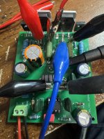
Really cool you got a working board together and running, gotta say I have never had so much fun in awhile playing around with diamond buffers.
Adding additional gain with another stage really wakes them up.
The folded drivers can be bootstrapped and the set resistors for current source can also be bootstrapped.
So many birds with one stone, more voltage swing and less early effect
- Home
- Amplifiers
- Solid State
- OpAmp driven diamond buffer amplifier