SWEEEEET, have you tested it with music? Can I use your design? I guess 1 thing I would change is to add a 8 pin dip socket/mount instead so that I can do some op-amp rolling~~~
this is only a "OK" design? It looks so fabulous coming from a DIY project and I assume there is no casing and heatsink yet? With all that resolved it would certainly be much better! anyways, i didn't see (did i miss it) decoupling caps anywhere for the op-amp... do you think it would help in any ways?
I thought they helped with clip recovery by limiting how quickly C1 could be charged to either rail voltage when Q1 and Q2 saturate, but I think it's a simulation artifact. I can make R2/R3 arbitrarily small as long as they're non-zero and still get rid of the adverse effect (i.e. voltage sag after clipping)No need for resistors R2/R3
That depends on what your expectations are, I guess. Is it high end audiophile gear? Far from it! It is a solid amplifier for casual listening at <20W? I think so, from what I've seen.this is only a "OK" design? It looks so fabulous coming from a DIY project and I assume there is no casing and heatsink yet? With all that resolved it would certainly be much better! anyways, i didn't see (did i miss it) decoupling caps anywhere for the op-amp... do you think it would help in any ways?
The biggest flaw is that the opamp will limit the voltage swing. A NE5532 takes away about 2V from each rail. You could mitigate that through various bootstrapping schemes, but that would defeat the purpose, since it's supposed to be simple with low parts count. But the NE5532 can handle +-22V on the rails, so assuming 18-19V peaks, you'd be able to push it up to 40-45W (peak) into 8ohm. Not sure that's a good idea, though. 20-25W is probably where this little amplifier performs best.
Yes, I've played music through it and it sounds good. I only have one channel so far, so it's hard to judge what the complete soundstage is like. My guess is it'll sound "clean" like any decent Class AB. Probably not the choice for someone who's into Class A with "warmth" and all that jazz.
And by the way, I shouldn't sit here and take all the credit. It was @No ideas who came up with it. I just tweaked it and built it. Really satisfying little project!
Nah, I'm a believer of mid-range product suffice. Truth be told measurement is just a number and I see no point pushing for the so called "TOTL" for numbers beyond our hearing range/capabilities. What is more important is the overall satisfaction coming from quality music/output. Like which human hears -140dB noise?That depends on what your expectations are, I guess. Is it high end audiophile gear? Far from it! It is a solid amplifier for casual listening at <20W? I think so, from what I've seen.
The biggest flaw is that the opamp will limit the voltage swing. A NE5532 takes away about 2V from each rail. You could mitigate that through various bootstrapping schemes, but that would defeat the purpose, since it's supposed to be simple with low parts count. But the NE5532 can handle +-22V on the rails, so assuming 18-19V peaks, you'd be able to push it up to 40-45W (peak) into 8ohm. Not sure that's a good idea, though. 20-25W is probably where this little amplifier performs best.
Yes, I've played music through it and it sounds good. I only have one channel so far, so it's hard to judge what the complete soundstage is like. My guess is it'll sound "clean" like any decent Class AB. Probably not the choice for someone who's into Class A with "warmth" and all that jazz.
My bookshelves speakers is running at 4ohm and I'm no where close to 40W, day usage probably somewhere 30W and at night maybe something like 20ish. So this amp is more than sufficient.
Many thanks to @njswede and @No ideas
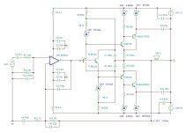
I seen now why you didn't think the 1000uF capacitor (C1) was enough of a "bootstrap". When driven close to clipping, it does lose its voltage boosting effect after a couple of seconds. See video below! When driven with bursts close to clipping, it works fine, so one could argue that it will be OK for most music, since it's rarely sustained max power. When you talk about bootstrapping to the emitter, do you mean tying the collector of the drivers to the emitter of the opposite output?The folded drivers can be bootstrapped and the set resistors for current source can also be bootstrapped
Attachments
you could also use an opa2134 since it haves a higher voltage swing etc.That depends on what your expectations are, I guess. Is it high end audiophile gear? Far from it! It is a solid amplifier for casual listening at <20W? I think so, from what I've seen.
The biggest flaw is that the opamp will limit the voltage swing. A NE5532 takes away about 2V from each rail. You could mitigate that through various bootstrapping schemes, but that would defeat the purpose, since it's supposed to be simple with low parts count. But the NE5532 can handle +-22V on the rails, so assuming 18-19V peaks, you'd be able to push it up to 40-45W (peak) into 8ohm. Not sure that's a good idea, though. 20-25W is probably where this little amplifier performs best.
Yes, I've played music through it and it sounds good. I only have one channel so far, so it's hard to judge what the complete soundstage is like. My guess is it'll sound "clean" like any decent Class AB. Probably not the choice for someone who's into Class A with "warmth" and all that jazz.
i just had an idea. i didnt have an idea for an account nameAnd by the way, I shouldn't sit here and take all the credit. It was @No ideas who came up with it. I just tweaked it and built it. Really satisfying little project!
Unfortunately, I just found out that the "boost" capacitor (C1) has a fatal flaw. It will actually become reverse bias when you approach clipping.you could also use an opa2134 since it haves a higher voltage swing etc.
I think this is a great utility amplifier with higher than normal performance. It's a great starting point if you want to expand on it. I really like Diamond buffers.
The boost cap probably won't suffer in use. With a peak to average ratio of 10:1 ~ 15:1 you won't be near clipping long enough to have a problem. Maybe in a car system - lol!
Hey No ideas,
When I originally joined, the names I prepared for signup were all taken. I didn't think you were supposed to use your real name, but that would have been okay. So this popped into my head. It is based on "analogue technician". "No ideas" can be amusing and all of us can be in that situation often enough!
Yes correct.When you talk about bootstrapping to the emitter, do you mean tying the collector of the drivers to the emitter of the opposite output?
Pretty cool screen capture
Amazing what technology can do these days. Nice equipment
Op amp stays about 2 volts from the rails before clipping, if it was rail to rail you would see more collapse if driven harder and then a crossover distortion
before it recovers. Was more pronounced with no ideas test circuits as well, that was just because a bd139/140 pair wont drive a 8 ohm load.
But essentially same circuit behavior before/after clipping or near the crest of the amplifier.
As mentioned good enough for the power levels of the circuit.
The trick to fix is less current demand on the folded drivers the capacitor is removed not needed. So instead of directly driving power transistors, a Darlington or CFP stage is used.
You wont need 20 to 30ma for the folded drivers. Only need 3ma to 6ma.
Fun stuff. Of course with a Darlington you need a extra voltage drop to bias they outputs. Or with CFP the single drop from the folded drivers works fine.
I think this experiment has reached its conclusion. To try to salvage the design, I swapped in a pair of Sanken MN1620 and NM2488 Darlingtons I had scavenged from an old Sony receiver. After fiddling with the bias for a while, I got it to work OK. But alas, it now suffers from thermal runaway. I guess it's because the hFE of the Darlingtons is so much higher than the BD139/140 in the folded pair. Oh well... I had fun and learned a lot along the way,
Darlington has 2 VBE drops and would need thermal tracking that also includes 2 VBE drops for bias/thermal trackingAfter fiddling with the bias for a while, I got it to work OK. But alas, it now suffers from thermal runaway
The folded drivers only provide 1 VBE drop. Works rather well for CFP
Regardless how it is done, the devices would all be thermally linked for Darlington.
With CFP only the folded drivers and drivers are thermally linked.
There is numerous ways to get 2 VBE drops for a darlington with folded drivers.
Some use resistors = nonsense. no thermal tracking for 2nd VBE
Some use diodes, typically doesn't track as well.
Or use transistor as diode which can be better thermally coupled ( TO-126 etc etc)
Or Current mirror which provides 1 additional VBE , same thing TO-126 thermally coupled
Or VBE multiplier again TO-126 thermally coupled . Where the multiplication is set for the output stage as any other traditional VBE circuit
The magic of diamonds, once VBE drops are established, with correct current. It is set and forget " auto bias"
Long as the current remains CONSTANT with unregulated voltage rails the bias is not affected or vary with rail voltage drops or peaks.
Resistors do not provide constant current with unregulated rails, to have constant current you need constant voltage.
Hence rather bootstrap, feedback or diode constant current sources. The current remains constant with a voltage reference.
The charged capacitor, diode or transistors provides this constant voltage, hence constant current is achieved.
Aside from numerous tradeoffs with a bootstrap CCS, for people that desire simple circuits or usually slightly higher voltage swing.
Bootstrap is rather fun and simple, or you get the fun of hearing people cry about them. lol
As with diode or feedback CCS having numerous benefits, the impedance will be 1 Meg or higher
opposed to bootstrap where the impedance is limited to the resistor values. If high current is needed the impedance will be rather poor.
Hence even with regulated rails a set resistor for current, depending on circuit such as differential input will still have poor impedance.
Last edited:
Here is extremely simplified bootstrap folded driver ( aka diamond) driving CFP ( Complementary Feedback Pair)
Showing only of course the buffer and missing the op amp front end / feedback
For 16 to 18 volt power rails. Since @njswede was concerned with excessive idle current. I'm with yah.
30 to 45ma is typically accepted as minimal and 100 to 120ma consider ideal for BJT power transistors.
CFP being used for example since only one VBE is needed and the folded drivers will provide all the needed
bias.

This shows added bootstrap current sources instead of ideal models.
And stills excludes power supply decoupling and any other desired gizmos.
decoupling being mandatory as with any other amplifier.
Gray box added showing how folded drivers and pre drivers are thermally coupled on same heatsink.
Basic normal stuff for CFP.

Showing only of course the buffer and missing the op amp front end / feedback
For 16 to 18 volt power rails. Since @njswede was concerned with excessive idle current. I'm with yah.
30 to 45ma is typically accepted as minimal and 100 to 120ma consider ideal for BJT power transistors.
CFP being used for example since only one VBE is needed and the folded drivers will provide all the needed
bias.
This shows added bootstrap current sources instead of ideal models.
And stills excludes power supply decoupling and any other desired gizmos.
decoupling being mandatory as with any other amplifier.
Gray box added showing how folded drivers and pre drivers are thermally coupled on same heatsink.
Basic normal stuff for CFP.
Last edited:
You can also bootstrap the folded drivers to the bootstrap current source capacitors.
Since no longer max current by using pre driver emitters, the resistor values are lowered to
achieve similar folded driver current. Pre driver resistors are raised for similar output current.
In a feedback loop this tends to achieve lowest THD. This example is tailored for minimum A/B bias
adjust to desired needs. 820 is the max minimum resistor value I will use for a bootstrap CCS.
If you want higher currents a typical transistor feedback CCS would be used
Last edited:
- Home
- Amplifiers
- Solid State
- OpAmp driven diamond buffer amplifier


