op amp macromodeling shortcuts can be a problem - but I did cut in my smplAD797 transistor level model and got 80 degrees phase margin @3 MHz intercept with some compensation tweaking
http://www.diyaudio.com/forums/solid-state/123613-class-biasing-ad797-6.html#post1525757 for the 797 asc
unmodeled device and layout parasitics may be problems, but with loop gain intercept in low/mid single digit MHz we're not really into serious RF design here - Cordell, Self already address amps in this speed range
higher order loop gain slope does have possible costs in clipping recovery - likely need to explore adding Baker Clamps, current limiters internally for rapid and clean clipping recovery - the 75 Ohm R for output bias would better be a shunt Vreg to sink overcurrents without introducing transient bias error
Last edited:
Jan Didden is using AD844 in bootstraping (Part 2 fig4)
paX: an error-correction power amp
http://www.linearaudio.nl/linearaudio.nl/images/pdf/UK-1_2008040241.pdf
http://www.linearaudio.nl/linearaudio.nl/images/pdf/UK-2_2008050441.pdf
paX: an error-correction power amp
http://www.linearaudio.nl/linearaudio.nl/images/pdf/UK-1_2008040241.pdf
http://www.linearaudio.nl/linearaudio.nl/images/pdf/UK-2_2008050441.pdf
Last edited:
Is it necessary to connect opamp output to amp output?
No, look R7 and R16 on FIG4
http://www.linearaudio.nl/linearaudio.nl/images/pdf/UK-2_2008050441.pdf
20Khz THD is better with SANYO :
.MODEL 2SC2911 NPN(IS=1.91E-13 ISE=4.9E-11 NF=1.073 NE=2.8 BF=274
+IKF=0.0836 VAF=320 CJC=6.4E-12 TF=8.84E-10 MJC=0.31 VJC=0.98
+CJE=6.4E-12 MJE=0.3 VJE=0.4 LEVEL=1)
.MODEL 2SA1209 PNP(IS=1.6E-13 ISE=5.2E-11 NF=1.073 NE=2.57 BF=257
+IKF=0.081 VAF=125 CJC=8.7E-12 TF=9.95E-10 MJC=0.313 VJC=0.975
+CJE=8.7E-12 MJE=0.3 VJE=0.4 LEVEL=1)
20Khz THD is better with SANYO :
.MODEL 2SC2911 NPN(IS=1.91E-13 ISE=4.9E-11 NF=1.073 NE=2.8 BF=274
+IKF=0.0836 VAF=320 CJC=6.4E-12 TF=8.84E-10 MJC=0.31 VJC=0.98
+CJE=6.4E-12 MJE=0.3 VJE=0.4 LEVEL=1)
.MODEL 2SA1209 PNP(IS=1.6E-13 ISE=5.2E-11 NF=1.073 NE=2.57 BF=257
+IKF=0.081 VAF=125 CJC=8.7E-12 TF=9.95E-10 MJC=0.313 VJC=0.975
+CJE=8.7E-12 MJE=0.3 VJE=0.4 LEVEL=1)
May I ask where you obtained these from and whether you checked them for accuracy ??
Hi
You do what schematic ?
With BC550 and MJE350 ?
Most likely starting from this one.
May I ask where you obtained these from and whether you checked them for accuracy ??
I'm not sure that is good, I found them on diyaudio
I change to (K)2SC3503 / (K)2SA1381 from CordellAudio.com - SPICE Models
Yes I will try in real life ... but :
On simulation I increased the voltage on OPAMP and lowered local feedback value
0.000082% 20K 100W 4ohm
0.000000 % 1K 100W 4ohm
https://sites.google.com/site/opampbasedamp/LTAMP.png
Somesay that amplifiers that use opamps supply pins to drive output stage is a very bad idea....
Somesay that amplifiers that use opamps supply pins to drive output stage is a very bad idea....
I am one of the some 🙂 it is a bad idea.
This depends on the current availability of the opamp and the current gain of the current amplifier.Somesay that amplifiers that use opamps supply pins to drive output stage is a very bad idea....
This can not make sweeping statements.
This depends on the current availability of the opamp and the current gain of the current amplifier.
This can not make sweeping statements.
The problem is that all internal currents and current fluctuations that may not be related to the signal are put forward to the OS, that is why I would say it is a bad idea. There are multiple way to convey the op-amp output signal to the OS and that will be a much cleaner way to do it.
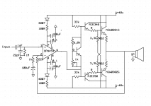
Heres one of the simple designs where pretty much everyone will understund how it works...
Ive built one and I think its a very good amplifier. Ive been running mine for over a month now at 4 ohms.. Yes 4R...
But never ran it with single pair at maximum power because I dont want to blow them up 🙂
Its quite efficient and sounds better than any chipamp there is.
The only problem with this design is that you need "HV OPAmp" because the voltage swing is limited to opamps.
http://s6.postimg.org/do70qhbtd/image.png
http://s6.postimg.org/dyldowg0h/image.png
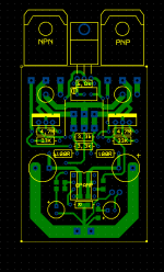
http://s6.postimg.org/avdt6gbgx/pcb.png
Special thanks for Mr geraldfryjr for sharing hes circuit .
Ive built one and I think its a very good amplifier. Ive been running mine for over a month now at 4 ohms.. Yes 4R...
But never ran it with single pair at maximum power because I dont want to blow them up 🙂
Its quite efficient and sounds better than any chipamp there is.
The only problem with this design is that you need "HV OPAmp" because the voltage swing is limited to opamps.
An externally hosted image should be here but it was not working when we last tested it.
http://s6.postimg.org/do70qhbtd/image.png
An externally hosted image should be here but it was not working when we last tested it.
http://s6.postimg.org/dyldowg0h/image.png
An externally hosted image should be here but it was not working when we last tested it.
http://s6.postimg.org/avdt6gbgx/pcb.png
Special thanks for Mr geraldfryjr for sharing hes circuit .
Last edited:
post75.
The top link does not lok right to me.
The crossover feeding into the Vbe multiplier is trying to arrange a voltage of 3k3/(33k+3k3) to the top of the Multi.
The other is feeding an inverted version.
i.e. about 18.2% of 40Vdc across the Multi.
But the Multi is trying to regulate that voltage back to the Vbias set point.
Does this arrangement work?
Please attach the pics.
Im such a dumbass sometimes.
Fixed schematic...
That PCB I made that day was prototype. I just wanted to try if its possible to dye PCB's with just ink and boiling... Seems to work.
Fixed schematic...
That PCB I made that day was prototype. I just wanted to try if its possible to dye PCB's with just ink and boiling... Seems to work.
Attachments
Last edited:
Its fine if you have preamp..
But 445 seems to be a better device and has FET input .
Ive tried this amp with OPA551/2 OPA27 sounds great, has no pops on startup and is silent when idle.
But Id rather run them with regulated power supply. The mains can vary as much as 5% or even more...
But 445 seems to be a better device and has FET input .
Ive tried this amp with OPA551/2 OPA27 sounds great, has no pops on startup and is silent when idle.
But Id rather run them with regulated power supply. The mains can vary as much as 5% or even more...
Last edited:
- Home
- Amplifiers
- Solid State
- Opamp based power amp