Hi Terry,
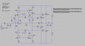
Output swing is 28 Vpeak. For a 4 Ohm load, output power is nearly 100 W.
I break the "main" feedback loop to inject signal for loop-gain analysis (LTspice file in post #37). I may be wrong. But the results (AC vs Trans) so far seem consistent.
I am trying this circuit with another high-speed opamp, LT1223. This circuit has opened my mind to consider non-audio-grade opamps (current feedback in particular) for audio applications. Very promising simulation results. Will it a real good audio amplifier in real world (measurement and sound)? I am eager to test it.
Cheers,
Panson
Last edited:
Panson, look the first paper : De la puce à l'oreille - Acoustique et lectroacoustique
JCB recomande LT and AD, imagine these diagram used on bootstrap
Q10,Q12,Q14,Q16, C14
JCB recomande LT and AD, imagine these diagram used on bootstrap
Q10,Q12,Q14,Q16, C14
Last edited:
higher loop gain is possible with LT1468 - it uses Scott's AD797 topology but not the big heavy bias input bjt so the input is better for higher input Z source
http://cds.linear.com/docs/en/lt-journal/LT1468_1198_Mag.pdf
(have to shunt some more current to bias the output Q the same, and adjust the compensation caps to get reasonable stability when changing op amps)
the circuit does seem too good to be true - where are the gremlins lurking?
maybe too many cascodes in the inner loop? - they still have poles that must add up?
I do think stability analysis is better with 2 loops cut, the outer conventional feedback and the inner R divider to the op amp output can both be cut with a single gain probe
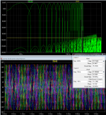
looking at the .tran distortion sim a interesting test is to use 2 sine inputs in series, 1:1 level of 600mV each to give near full output, fix one at 20 KHz, step the other from 1k to 19k in 1 kHz steps - the critical measure of quality is the IMD products below 20 kHz - also has the harmonic distortions of the lower tone
when this stepped 2-tone is done you can plot the combined fft, see just how "bad" the "rising distortion with frequency" is (not)
the yellow line is ~ -120 dB re the peak of the combined 2 tones
you can see all audio frequency harmonics of the 1-19 kHz stepped frequency tones and the IMD difference products of all orders with the 20 kHz constant tone
all audio frequency distortions just barely breaks above -120 dB below the combined 2 tone peak amplitude in the 18, 19 kHz bins - with the original op amp
the level of all of the audio band distortions are all inaudible - below human hearing threshold in quiet if the speaker were giving 120 dB SPL with the amp's full output
with higher loop gain op amp you can keep every audio frequency distortion product below -120 dB in the sim
http://cds.linear.com/docs/en/lt-journal/LT1468_1198_Mag.pdf
(have to shunt some more current to bias the output Q the same, and adjust the compensation caps to get reasonable stability when changing op amps)
the circuit does seem too good to be true - where are the gremlins lurking?
maybe too many cascodes in the inner loop? - they still have poles that must add up?
I do think stability analysis is better with 2 loops cut, the outer conventional feedback and the inner R divider to the op amp output can both be cut with a single gain probe
looking at the .tran distortion sim a interesting test is to use 2 sine inputs in series, 1:1 level of 600mV each to give near full output, fix one at 20 KHz, step the other from 1k to 19k in 1 kHz steps - the critical measure of quality is the IMD products below 20 kHz - also has the harmonic distortions of the lower tone
when this stepped 2-tone is done you can plot the combined fft, see just how "bad" the "rising distortion with frequency" is (not)
the yellow line is ~ -120 dB re the peak of the combined 2 tones
you can see all audio frequency harmonics of the 1-19 kHz stepped frequency tones and the IMD difference products of all orders with the 20 kHz constant tone
all audio frequency distortions just barely breaks above -120 dB below the combined 2 tone peak amplitude in the 18, 19 kHz bins - with the original op amp
the level of all of the audio band distortions are all inaudible - below human hearing threshold in quiet if the speaker were giving 120 dB SPL with the amp's full output
with higher loop gain op amp you can keep every audio frequency distortion product below -120 dB in the sim
Attachments
Last edited:
0.000012% 1K 100W 4ohm with LT1363
LT1468 dont work on my schematic
LT1468 dont work on my schematic
Attachments
Last edited:
You might find it interesting that even very theoretically brilliant people such
as B Putzeys have similar views WRT the distortion versus Fr characteristics
(as far as I am aware).
T
Bruno said these things as a technical justification for the sound quality of basic hypex amplifier class D modules. As as you can see he has since developed NCORE which does not have constant distortion with frequency. These amps are sold on the grounds they sound better because they have much lower distortion. Bruno strongly believes that huge amounts of feedback is needed to correct the distortion produced by power amplifiers.
Last edited by a moderator:
Bruno said these things as a technical justification for the sound quality of basic hypex amplifier class D modules. As as you can see he has since developed NCORE which does not have constant distortion with frequency. These amps are sold on the grounds they sound better because they have much lower distortion. Bruno strongly believes that huge amounts of feedback is needed to correct the distortion produced by power amplifiers.
From what I can see, Ncore is similar, in fact appears to have even more constant
distortion versus frequency (and power) - just a lot lower. Check the data sheet.
Last edited:
0.000012% 1K 100W 4ohm with LT1363
LT1468 dont work on my schematic
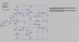
You will need to modify the circuit slightly and/or component value to avoid oscillation since the chip has a different open-loop response.
When I replaced LT1363 by LT1223, I needed to do so in order to avoid oscillation. LT1223 is a current-feedback amp without high-impedance at inverting input. Feedback resistor must follow data sheet suggested values.
The circuit is now running.
THD (28Vp swing)
1 k 0.000329%
10 k 0.000169%
20 k 0.000653%
Attachments
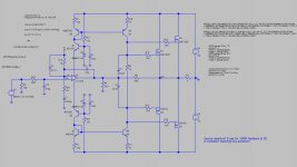
My new schematic with LT1223 and 10p !!
THD (28Vp swing) (100W 4ohm)
1 k 0.000003% !!!!!!!!!!!!!!
20 k 0.000475%
THD (28Vp swing) (100W 4ohm)
1 k 0.000003% !!!!!!!!!!!!!!
20 k 0.000475%
Last edited:
I came across some pre-packaged op-amp power amplifiers, the output-stage schematics may be useful for your designs?
http://www.farnell.com/datasheets/28867.pdf
http://www.farnell.com/datasheets/28911.pdf
http://www.farnell.com/datasheets/28867.pdf
http://www.farnell.com/datasheets/28911.pdf
You will need to modify the circuit slightly and/or component value to avoid oscillation since the chip has a different open-loop response.
When I replaced LT1363 by LT1223, I needed to do so in order to avoid oscillation. LT1223 is a current-feedback amp without high-impedance at inverting input. Feedback resistor must follow data sheet suggested values.
The circuit is now running.
THD (28Vp swing)
1 k 0.000329%
10 k 0.000169%
20 k 0.000653%
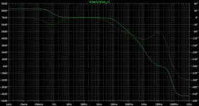
Looks good but phase margin at 1MHz is not very good.
I have found similar phase response with various multi order compensation
schemes. They can be tricky to get right.
I would suggest doing square wave testing with various cap loads to see how
stable it is. Obviously you will have to put the OP LR network on.
0.000309% 20K 😱
My simulation showed loop-gain not lower than 50 dB up to ~100 kHz. If the open-loop THD at 20k is 0.1%, closed-loop will be theoretically ~0.1/316 = 0.000316%. Well, my loop-gain analysis might be wrong or not accurate.
Looks good but phase margin at 1MHz is not very good.
I have found similar phase response with various multi order compensation
schemes. They can be tricky to get right.
I would suggest doing square wave testing with various cap loads to see how
stable it is. Obviously you will have to put the OP LR network on.
Good point! I will add output network (LR and Zobel) to try reactive loads.
looking at the .tran distortion sim a interesting test is to use 2 sine inputs in series, 1:1 level of 600mV each to give near full output, fix one at 20 KHz, step the other from 1k to 19k in 1 kHz steps - the critical measure of quality is the IMD products below 20 kHz - also has the harmonic distortions of the lower tone
Cool! Thanks, jcx.
Last edited:
0.000309% 20K 😱
I did a bode plot of this version with open loop gain versus phase.
Unfortunately it is not close to being stable. You cant get all that
open loop gain for free. 🙂
I think it's a good idea to start focusing on getting these designs
working first with good phase margin and stability into reactive
loads then start trying to knock the distortion down.
T
Panson, look the first paper : De la puce à l'oreille - Acoustique et lectroacoustique
JCB recomande LT and AD, imagine these diagram used on bootstrap
Q10,Q12,Q14,Q16, C14
Sorry, would you mind to post the link of the paper.
I found this one http://ddata.over-blog.com/xxxyyy/1/74/30/05/mybook/CRetVx.pdf interesting, though I don't know French.
The site seems to have lots of useful information. Thanks!
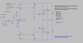
I am analyzing the circuit by simplifying it. Some components are removed without affecting circuit operation. Bootstrapping transistors removed and voltage reduced. Is it necessary to connect opamp output to amp output? As long as we have current swing in current mirror, output FETs will function as intended. Right? In the simplified test circuit (shown below), opamp output is simply grounded via a resistor. I have not fully checked it. TRANS simulation run without problem. THD for 1k, 10k and 20k not affected compared to original circuit.
Attachments
Guys, so unreal. OP amps are too idealistically simmed. Build, measure & see.
Even sch from my post in reality can't achieve these surreal numbers.
Regards L.C.
Even sch from my post in reality can't achieve these surreal numbers.
Regards L.C.
Guys, so unreal. OP amps are too idealistically simmed. Build, measure & see.
Even sch from my post in reality can't achieve these surreal numbers.
Regards L.C.
Yes, the numbers are too good to be true.
That is what I am after - building a real one. Real circuit inferior to simulation or even not working is a norm. We can then learn more (learning from fails). The opamp models are most likely macro models instead of transistor level. Nevertheless, IMHO we have something to start with.
Guys, so unreal. OP amps are too idealistically simmed. Build, measure & see.
Even sch from my post in reality can't achieve these surreal numbers.
Regards L.C.
Very true.
There are ways to prove this. I tested the .asc with 470 ohm source
impedance and then with 10k source impedance at 20kHz 30V pk OP.
The distortion results were almost identical. This will -never- happen in real
life due to the common mode distortion induced by the high source
impedance, especially at 20kHz.
With discrete designs and decent models I can get a decent representation
of CM distortion with higher source impedances.
Bottom line - I don't think these numbers are a reality.
T
Member
Joined 2009
Paid Member
You are in danger of getting off-track with this - the THD numbers quoted are all so tiny that their differences are irrelevant - the practicality of the circuit layout will dominate. You should get yourself a few op-amps on order, some prototype board and a speaker protection circuit, an oscilloscope and start playing ! 😀
Yes, thats also my opinion. I understand the results of LT as direction in what I have to moveYou are in danger of getting off-track with this - the THD numbers quoted are all so tiny that their differences are irrelevant - the practicality of the circuit layout will dominate. You should get yourself a few op-amps on order, some prototype board and a speaker protection circuit, an oscilloscope and start playing !

- Home
- Amplifiers
- Solid State
- Opamp based power amp