Hi All,
I have been regitered here for a while now, but haven't made any contributions
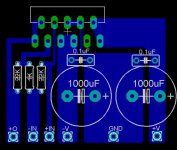
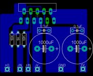
I was wondering if you guys would be so kind as to have a look at my OPA549 Gainclone design.
My design is just "copies" of others I have seen, and jumbled around a bit to make it my own 😉
I'm new to circuit design so all comments, tips and suggetions are welcome.
I will post the eagle file incase anyone wants a closer look.
But for now here is a screen shot:
I have been regitered here for a while now, but haven't made any contributions
I was wondering if you guys would be so kind as to have a look at my OPA549 Gainclone design.
My design is just "copies" of others I have seen, and jumbled around a bit to make it my own 😉
I'm new to circuit design so all comments, tips and suggetions are welcome.
I will post the eagle file incase anyone wants a closer look.
But for now here is a screen shot:
Attachments
also the gain is too high for the OPA549.
You have a voltage gain of (22/1+1=) 23.
Try something like 11. (1k and 10k resistors.)
You have a voltage gain of (22/1+1=) 23.
Try something like 11. (1k and 10k resistors.)
These chips need a low gain because of their low GBP, but remember that with a gain of 11 you need some more gain in another stage like an active preamplifier (or just an opamp circuit in the amp). I use a voltage gain of 3 in my DIY preamp, and 3 x 11 = 33 which would be sufficient.

+ a little Eagle tips:
Try to use a standard grid of something like 50 mils or 25 mils (grid set to inch) instead of 0.0001mm or what you were using. With that grid it is almost impossible to put the components/traces where you want them.
Try to use a standard grid of something like 50 mils or 25 mils (grid set to inch) instead of 0.0001mm or what you were using. With that grid it is almost impossible to put the components/traces where you want them.
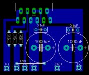
Ok i have thickened up the output trace, will this now be thick enough to handle 8A?
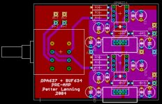
I am also planning to make an active preamp using opa627 and buf634, but have not yet decided on chip configurations yet.
I will attempt this once i get some more experience under my belt 🙂
I am also planning to make an active preamp using opa627 and buf634, but have not yet decided on chip configurations yet.
I will attempt this once i get some more experience under my belt 🙂
Attachments

Alcaid said:Instead of using a jumper, you could connect SG-PG like this:
(The PCB will be a little bigger though)
LOL you beat me too it alcaid that was my next question, or could i join pins 3, 6 and 8 as they all connect to ground? or does this cause other problems?
Attachments
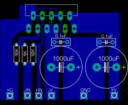
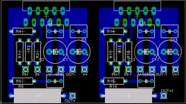
n00beR said:I have applied your suggestions Alcaid, nd have attached the new image below.
Would this implementation suffice?
Still missing the fat ouput trace. 100 mils ( 2.54mm) wide trace should do the job. 🙂

The trace you made wider in the last picture isn't needed, that's pin 3 (IN-).
Only the supply pins (V+: pin 10 & 11) (V-: pin 5 & 7) and the output (pin 1 & 2) needs fat traces.
The other ones are only carrying low current signal (I use 32 mils wide trace for these).
Only the supply pins (V+: pin 10 & 11) (V-: pin 5 & 7) and the output (pin 1 & 2) needs fat traces.
The other ones are only carrying low current signal (I use 32 mils wide trace for these).
I've done it like the picture below:
I use other caps however, 100uF + 100nF, and separate PSU (High Cap Unregulated PSU like CarlosFM's design).
Also I have added a zobel to the output and an 0R1 wirewound output resistor (so I can parallell them).
Still waiting for the trafo so I can listen to them though....
I use other caps however, 100uF + 100nF, and separate PSU (High Cap Unregulated PSU like CarlosFM's design).
Also I have added a zobel to the output and an 0R1 wirewound output resistor (so I can parallell them).
Still waiting for the trafo so I can listen to them though....
Attachments
Hi Alcaid,
Nice design, wold you be so kind as to send me your eagle files?
It would be greatly appreciated
Nice design, wold you be so kind as to send me your eagle files?
It would be greatly appreciated
Alcaid said:also the gain is too high for the OPA549.
You have a voltage gain of (22/1+1=) 23.
Try something like 11. (1k and 10k resistors.)
Alcaid
on the datasheet(Open-loop gain and phase vs frequency)It looks like for a gain of 30 its flat up to 60k is that right?
- Status
- Not open for further replies.
- Home
- Amplifiers
- Chip Amps
- OPA549 Gainclone Layout