They are actually from windmills that produce electricity.mind me asking where those heatsinks came from?
I am lucky enough to know a guy with the right connections😎
Some component in a windmill gets very hot at startup, and needs a large heatsink. They are usefull for a hefty class A amp also🙂
Steen.
Posted some pictures of my amp + pre.
http://www.diyaudio.com/forums/showthread.php?s=&threadid=53220
http://www.diyaudio.com/forums/showthread.php?s=&threadid=53220
I built one too
I built this amp in one weekend.
But it's not cased yet...that may take 3 or 4 weekends for me 😀
I used Alcaid's OPA549 schematic, 330uf caps. The board for each channel is 1 3/4 inches square, point-to-point wired.
I made sure to "double up" on the wire thickness in the power input lines to the chip, as well as the ground, and the signal Out.
But for the buffer, I tested it with this circuit, as I had it built already for another project :
Page 22,
fig. 6-53
http://waltjung.org/PDFs/ADI_2002_Seminar_Ch6_Audio_Drivers_I.pdf
---------------
For this amp, I might build a similiar driver/buffer earlier in that PDF,
page 20,
fig. 6-51
where for a gain of 3, changes would be:
R1=3k
R2=1k
R3=1k
R4=1k
using a dual 50k audio taper pot in the front.
=RR=
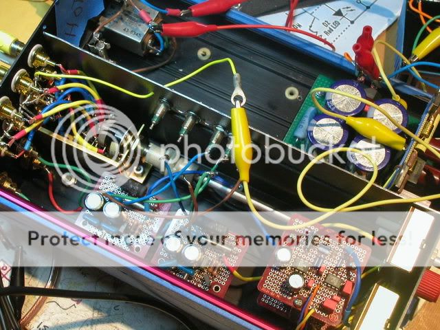
Pics of finished opa549 integrated amp..
(Thanks for the amp schemo, Alcaid !!)
Inside overview (minus Xformer, for grounding test)
Chip amp view:
http://i5.photobucket.com/albums/y177/Midiot/DSCN2056.jpg
Preamp view:
http://i5.photobucket.com/albums/y177/Midiot/DSCN2060.jpg
PSU (cap multiplier for the Chipamps + pre-regulator (esp website) and 78/7915 regulated for the Preamps....showing voltages - loaded.)
http://i5.photobucket.com/albums/y177/Midiot/DSCN1927.jpg
Exterior:
http://i5.photobucket.com/albums/y177/Midiot/DSCN2064.jpg
Sounds real good for a small secondary system. It drives those NHT bookshelf's to their limit. 4 inputs + a pair Out (off the switch) for a headphone amp. No offset cap between pre and amp...maybe I should have those ??
??
I have not calculated the Watts RMS yet....(I've got that formula somewhere.. )
)
=RR=
(Thanks for the amp schemo, Alcaid !!)
Inside overview (minus Xformer, for grounding test)
An externally hosted image should be here but it was not working when we last tested it.
Chip amp view:
http://i5.photobucket.com/albums/y177/Midiot/DSCN2056.jpg
Preamp view:
http://i5.photobucket.com/albums/y177/Midiot/DSCN2060.jpg
PSU (cap multiplier for the Chipamps + pre-regulator (esp website) and 78/7915 regulated for the Preamps....showing voltages - loaded.)
http://i5.photobucket.com/albums/y177/Midiot/DSCN1927.jpg
Exterior:
http://i5.photobucket.com/albums/y177/Midiot/DSCN2064.jpg
Sounds real good for a small secondary system. It drives those NHT bookshelf's to their limit. 4 inputs + a pair Out (off the switch) for a headphone amp. No offset cap between pre and amp...maybe I should have those
??I have not calculated the Watts RMS yet....(I've got that formula somewhere..
)=RR=
I etched Alcaid's PCBs to find out that all my drill bits except bent 2mm one are missing... Anyhow I just love your schematic and PCB!
It will be nice 2x10W@8Ohm/2x20W@4Ohm amplifier when finished 🙂 That will happen in few days, I hope.
It will be nice 2x10W@8Ohm/2x20W@4Ohm amplifier when finished 🙂 That will happen in few days, I hope.
Alcaid said:Posted some pictures of my amp + pre.
http://www.diyaudio.com/forums/showthread.php?s=&threadid=53220
JannaCassandra said:How much power will i get with OPA549 using +/- 25V?
Something around 40W with 4Ohm load or twice less with 8Ohm.
Yesterday finished quick and dirty versiom of my OPA549 "gainclone" based on Alcaid's schematic and PCB. Although I'm using cheap components, comparing to amplifier I was using before it sounds great. I hope to finish it properly so I could show everyone my idea of low power HiFi amplifier 🙂
Thanks to Alcaid for such a nice version of this amp 🙄
Thanks to Alcaid for such a nice version of this amp 🙄
Alcaid said:Here is the schematic of my psu.
A zener emitter follower.
(The symbol for the J511 is wrong, this a CCS).
Am I correct to say that the voltage can be changed simply by changing the appropriate zener ?
- Status
- Not open for further replies.
- Home
- Amplifiers
- Chip Amps
- OPA549 Gainclone Layout