I tried a 1K across the ghost channel RCA input and the output ghost disappeared. Yes a balanced connection would usually cancel out a ghost IF it existed on both +and - wires.Are you shorting out the 'unoccupied' input or at least using something akin to a cartridge. If the input is open circuit, I'd expect to see 'some' crosstalk.
Only a fully balanced input would show 'low' crosstalk when OC.
I lied when I said that with 1K shunt on the ghost input channel the ghost output was gone. Yesterday I saw a true shorting plug in my bench mess and tried that. Ghost output got cleaner. With the scope's minimum 10mV vertical res, I could now see that I missed something with the 1K plug. 4.4mV across 1K = 4.4uA! That's 4400x the op asmp's Ib. See pics taken yesterday before the following steps done yesterday and today.Regarding @JRA 's crosstalk: does it get better when you terminate the unused right-channel input with some impedance well below 47 kohm? When you short it, for example?
I've ordered new Rs and Cs for repositioning of C2 and C20. I found a Pany 2.2uF metallized-PP with 7.5mm lead spacing that should go in, albeit tall. > > I've solder-coated the two outside +/- rails and the two outside Gnd rails with no change.
I tried running the "orange" wire on the board's backside but got similar results as the original positioning. = no help.
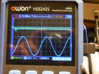
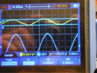
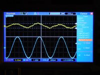
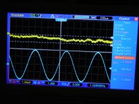
As before: Blue = driven Left channel output (8V) and Yellow = ghost Right channel output. Input signal = 40mVpp = 14.1mVrms
Attachments
Last edited:
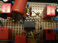
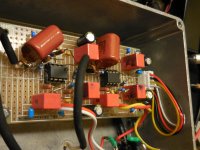
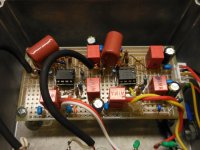
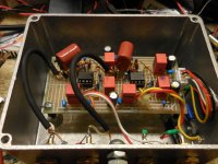
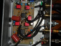
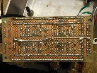
With four new input Rs (R13/130 and R6/60) and two new input Cs (C2 and C20) the new layout looks like the attached. The Left I/O occupies the bottom of the board and the Right I/O the upper part. Much more symmetrical. R13, R130, R6, R60, C2 and C20 are all new and were moved per the new ***'y re-org. C2 and C20 are now Panasonic metallized PP. The R/L Input connections are now shielded, lapel microphone coax.
Will provide pics tomorrow but the results are much like that taken for the above, #622 "1K plug" EXCEPT for the lack of the 1K plug. IOW, now with nothing occupying the Right input RCA the Ghost output signal is down into the single-digit mV range. A big improvement but it's still "there"..??? ~60dB separation.
Will provide pics tomorrow but the results are much like that taken for the above, #622 "1K plug" EXCEPT for the lack of the 1K plug. IOW, now with nothing occupying the Right input RCA the Ghost output signal is down into the single-digit mV range. A big improvement but it's still "there"..??? ~60dB separation.
Attachments

Well, I lied again when I wrote:
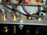
Take a look at the pics and please critique, suggest, scorn, etc. Where is it coming from now? Also see the latest "The board layout 6/7/2025" and note the shielded input cables. The side-lane Gnds are now only used for the +/- 15V bypass caps and the Output RCA returns. The rearranged input Rs now use the fat backbone shield Gnd. I guess the RCA out returns could use that Gnd as well....
Post #622 pic titled "1K plug" showing 4.4mVpp was taken with a mistake present from the layout re-do. I forgot to remove the two original 63.4K R6s when I added the two new R6s so that pic and the other are with "R6" = 31.7K. Follow...? I'm sorry. I did not discover this goof-ball mistake until after I took a bunch of new pics of the board so today's pics show the old R6 in-place. I was too lazy to repeat them so please ignore or see if you can find them. BUT today's scope shots are with the old R6 removed. The new No plug Ghost is 9.2mVpp down from 70mVpp in post #613 . And today's "1K plug" is now zip - at least on the 10mV scale. That's a big improvement but still there. Not gone.Will provide pics tomorrow but the results are much like that taken for the above, #622 "1K plug" EXCEPT for the lack of the 1K plug. IOW, now with nothing occupying the Right input RCA the Ghost output signal is down into the single-digit mV range. A big improvement but it's still "there"..??? ~60dB separation.
Take a look at the pics and please critique, suggest, scorn, etc. Where is it coming from now? Also see the latest "The board layout 6/7/2025" and note the shielded input cables. The side-lane Gnds are now only used for the +/- 15V bypass caps and the Output RCA returns. The rearranged input Rs now use the fat backbone shield Gnd. I guess the RCA out returns could use that Gnd as well....
Attachments
-
The board layout - CORRECTED 6-7-2025.pdf277 KB · Views: 69
-
 1K plug.JPG523.6 KB · Views: 73
 -
 No plug.JPG499.9 KB · Views: 70
 -
 No plug 9.2mVpp Ghost.JPG463.4 KB · Views: 71
 -
 No plug 4Vpp signal & 9.2mVpp Ghost.JPG483.8 KB · Views: 75
 -
 Close 6 - old R6.JPG374.1 KB · Views: 82
 -
 Close 5.JPG413.9 KB · Views: 82
 -
 Close 4.JPG428.5 KB · Views: 79
 -
 Close 3.JPG404.2 KB · Views: 79
 -
 Close 2.JPG424.5 KB · Views: 81
 -
 Close 1.JPG442.6 KB · Views: 77
Since my last post I’ve continued to try to track down the cause the Ghost signal appearing on the undriven Right channel output while the Left channel is driven by 1KHz, 20mVpp. Previously the Right channel RCA input was either unoccupied or occupied by a 0Ω shorting plug or a plug bridged with a 1K R while readings were taken from the Right output. When an identical of the Left channel signal appears in the Right channel I think of it as cross-talk or channel-bleed. The design under test is a stereo RIAA phono cart pre-amp using a single op amp for each of the identical R and L EQ circuits. In this case the phenomenon happens in only one direction. There is no crosstalk or bleed-over seen on the Left output when the Right channel is driven and the Left input is left unoccupied.
Op amp manufacturers make a big deal of their dual-op amp’s crosstalk values claiming 100dB and up, over the audio frequency range. After a lot of rip-up and replacements this attempt of mine can’t get beyond 60dB of chan↔chan separation – using two separate op amp ICs.
Things done so far:
1) The WIMA MKS2, C2(C20) input Cs were replaced with Panasonic 2.2uF MKPs. Both C2 and C20 were moved much closer to the other critical components surrounding U1 and U2, resp.
2) R13(R130) and R6(R60) were also relocated with C2(C20) and their Gnds were changed from the outside rail Gnd to the center backbone Gnd.
3) The input wires from the R&L input jacks were replaced with shielded microphone cable.
4) The output wires to the R&L output jacks were replaced with shielded microphone cable.
5) The RCA output and input cable returns (now the shields) were moved from the outside rail Gnd to the center backbone Gnd.
6) The thin copper outside rail Gnds and the ±15V outside rails were wetted with solder.
Note: At this point the only use of the outside rail Gnds is for C7 and C70.
7) The two OPA 627s were swapped and then changed to two TLE2071 op amps and then changed back.
8) The Left output (4Vpp) was loaded with a 1KΩ R.
9) C2 and C20 were shorted out and then returned to normal.
10) The I/O cables were moved around.
11) The added bypass caps initially tacked across C2-C20, C7-C70 and C8A & B were removed.
12) Screamed at the stars.
Results:
-- #7 - 12 had no effect.
-- #1 – 6 had the cumulative effect of dropping the unoccupied “No plug” Right input Ghost output reading from 9.2mVpp to 4.4mVpp and to near-0dB with the 1K plug inserted with the usual 20mVpp Left channel input and its 4Vpp output. IOW, the Ghost is now ~60dB below the driven signal.
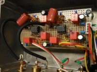
Attached are pics of the latest topside build; the latest layout dwg; pics of the board’s backside and a current schematic. Different scope was used with 5mV scale. Yellow=Right channel = U1. Blue=Left channel = U2
My rant follows:
At this point this is a freaking unsolved mystery and is unusable for my purposes. I can’t have a spurious voltage being output from an unmodulated wall of a groove. Those who actually check cartridge azimuth have a Test LP with:
Track 1 = both groove channel walls cut with identical 1KHz excursions.
Track 2 = cut with that same 1KHz on one groove wall and nothing on the other wall (i.e. smooth, silent).
Track 3 = cut opposite of Track 2.
Track 1 should produce two sinewaves of near equal voltage. They should measure within the cart maker’s spec for Balance (i.e. ± 1.5dB). If not close, stop right there.
Track 2 and 3 should produce one strong sinewave matching that from the same Track 1 wall and there will always be a weak 1KHz signal seemingly created by the smooth wall. Track 2 and Track 3’s silent smooth wall outputs can/may be wildly different and are typically in 10s of millivolts. The difference between the smooth wall and driven wall voltage determines the channel separation/crosstalk. And, there’s a L→R separation and a R→L separation to be concerned with. It all depends on how perpendicular the stylus’ center-line is to the groove and how well the coils and magnets are aligned.
So when adjusting the cant of the cart’s stylus in order to keep the driven wall output high and the (spurious) smooth wall signal as low as possible, a pre amp with an inherent bleed-through Ghost signal is not good. So where is it coming from?
Math?
- Both U1 Right and U2 Left have a gain of 200 @1KHz.
- A Right Ghost output of 4.4mVpp would suggest there is 22uVpp sitting at U1’s + input pin 3 presumably put there by U2’s input circuitry, feedback circuitry and/or 4Vpp output.
- It seems reasonable that to create 22uVpp @1KHz across U1’s input network of R6, C2 and R13, roughly 470pA of leakage or sneak current @1KHz would need to be available, sourced through a path from U2 Left..? How so?
-> Shorting U2’s 4Vpp output to Gnd through the 100Ω R40 kills U1’s Ghost output.
-> Driving the Left with a square wave produces a double-exponential output (i.e. rise and fall) waveform where the Ghost resembles the square wave. The Ghost is always in-phase.
-> And in the reverse scenario with Right being the driven channel, there is no Left Ghost bleed.
-> The above suggests that there is no leakage or sneak path between the Right channel and the Left.
What's next? Ideas, comments? Thanks for reading.
Op amp manufacturers make a big deal of their dual-op amp’s crosstalk values claiming 100dB and up, over the audio frequency range. After a lot of rip-up and replacements this attempt of mine can’t get beyond 60dB of chan↔chan separation – using two separate op amp ICs.
Things done so far:
1) The WIMA MKS2, C2(C20) input Cs were replaced with Panasonic 2.2uF MKPs. Both C2 and C20 were moved much closer to the other critical components surrounding U1 and U2, resp.
2) R13(R130) and R6(R60) were also relocated with C2(C20) and their Gnds were changed from the outside rail Gnd to the center backbone Gnd.
3) The input wires from the R&L input jacks were replaced with shielded microphone cable.
4) The output wires to the R&L output jacks were replaced with shielded microphone cable.
5) The RCA output and input cable returns (now the shields) were moved from the outside rail Gnd to the center backbone Gnd.
6) The thin copper outside rail Gnds and the ±15V outside rails were wetted with solder.
Note: At this point the only use of the outside rail Gnds is for C7 and C70.
7) The two OPA 627s were swapped and then changed to two TLE2071 op amps and then changed back.
8) The Left output (4Vpp) was loaded with a 1KΩ R.
9) C2 and C20 were shorted out and then returned to normal.
10) The I/O cables were moved around.
11) The added bypass caps initially tacked across C2-C20, C7-C70 and C8A & B were removed.
12) Screamed at the stars.
Results:
-- #7 - 12 had no effect.
-- #1 – 6 had the cumulative effect of dropping the unoccupied “No plug” Right input Ghost output reading from 9.2mVpp to 4.4mVpp and to near-0dB with the 1K plug inserted with the usual 20mVpp Left channel input and its 4Vpp output. IOW, the Ghost is now ~60dB below the driven signal.
Attached are pics of the latest topside build; the latest layout dwg; pics of the board’s backside and a current schematic. Different scope was used with 5mV scale. Yellow=Right channel = U1. Blue=Left channel = U2
My rant follows:
At this point this is a freaking unsolved mystery and is unusable for my purposes. I can’t have a spurious voltage being output from an unmodulated wall of a groove. Those who actually check cartridge azimuth have a Test LP with:
Track 1 = both groove channel walls cut with identical 1KHz excursions.
Track 2 = cut with that same 1KHz on one groove wall and nothing on the other wall (i.e. smooth, silent).
Track 3 = cut opposite of Track 2.
Track 1 should produce two sinewaves of near equal voltage. They should measure within the cart maker’s spec for Balance (i.e. ± 1.5dB). If not close, stop right there.
Track 2 and 3 should produce one strong sinewave matching that from the same Track 1 wall and there will always be a weak 1KHz signal seemingly created by the smooth wall. Track 2 and Track 3’s silent smooth wall outputs can/may be wildly different and are typically in 10s of millivolts. The difference between the smooth wall and driven wall voltage determines the channel separation/crosstalk. And, there’s a L→R separation and a R→L separation to be concerned with. It all depends on how perpendicular the stylus’ center-line is to the groove and how well the coils and magnets are aligned.
So when adjusting the cant of the cart’s stylus in order to keep the driven wall output high and the (spurious) smooth wall signal as low as possible, a pre amp with an inherent bleed-through Ghost signal is not good. So where is it coming from?
Math?
- Both U1 Right and U2 Left have a gain of 200 @1KHz.
- A Right Ghost output of 4.4mVpp would suggest there is 22uVpp sitting at U1’s + input pin 3 presumably put there by U2’s input circuitry, feedback circuitry and/or 4Vpp output.
- It seems reasonable that to create 22uVpp @1KHz across U1’s input network of R6, C2 and R13, roughly 470pA of leakage or sneak current @1KHz would need to be available, sourced through a path from U2 Left..? How so?
-> Shorting U2’s 4Vpp output to Gnd through the 100Ω R40 kills U1’s Ghost output.
-> Driving the Left with a square wave produces a double-exponential output (i.e. rise and fall) waveform where the Ghost resembles the square wave. The Ghost is always in-phase.
-> And in the reverse scenario with Right being the driven channel, there is no Left Ghost bleed.
-> The above suggests that there is no leakage or sneak path between the Right channel and the Left.
What's next? Ideas, comments? Thanks for reading.
Attachments
-
 New build_2 6-16-25.JPG483.7 KB · Views: 23
 -
 New build_4 6-16-25.JPG503.6 KB · Views: 24
 -
 New build_5 6-16-25.JPG401.5 KB · Views: 20
 -
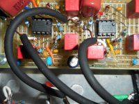
 U1 New build_3 6-16-25.JPG421.9 KB · Views: 19
 -
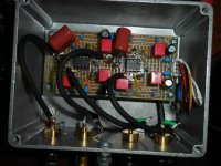 New build topside 6-16-25.JPG471.3 KB · Views: 24
 -
 New build bottom 6-10-25.JPG529.6 KB · Views: 23
 -
 New build - no plug 6-16-25.JPG410.7 KB · Views: 22
 -
 New build - 1K plug 6-16-25.JPG468 KB · Views: 19
 -
The board layout - CORRECTED 6-18-25.pdf281.6 KB · Views: 12
-
OPA627 R8 and R9.pdf322 KB · Views: 15
-> Shorting U2’s 4Vpp output to Gnd through the 100Ω R40 kills U1’s Ghost output.
If I understand you correctly, this means you short it at the output connector, so the op-amp still delivers an output signal. It drives R40 with a current swinging all the way from -20 mA to +20 mA. As R40 is placed right next to the output connector, the left-channel voltage swings at the board are still the same, the current swings are larger than they normally are and the crosstalk disappears anyway. This seems very strange to me.
-> Driving the Left with a square wave produces a double-exponential output (i.e. rise and fall) waveform where the Ghost resembles the square wave. The Ghost is always in-phase.
So the left channel signal is as you would expect due to the RIAA correction and the crosstalk on the right looks like the original uncorrected square wave signal?
These days I have quite good insight at some semiconductor manufactures and the data behind datasheets. Datasheets have, I would say, always promises they can keep and exceed. In order to get 100 dB channel separation it's all about the design, how to avoid capacitive and inductive coupling. In your case you could switch to SMD parts, a multilayer pcb with groundplanes. Check out how Quant Asylum has done their pcb's with extreme performance. My guess is that they have used at least 4-layer pcb. Photo borrowed from the youtube clipOp amp manufacturers make a big deal of their dual-op amp’s crosstalk values claiming 100dB and up, over the audio frequency range. After a lot of rip-up and replacements this attempt of mine can’t get beyond 60dB of chan↔chan separation – using two separate op amp ICs.
Yes. It makes no sense to build such circuit on a breadboard with random wiring, when one tries to get some good parameters. And then endless posts and descriptions. Wasting time.
You understand correctly Marvel but I screwed up. I just tried that again, got the same result but the damn Right chan cable is loose-fitting so futzing with the Left shorting plug made the Right drop out. Sorry again.If I understand you correctly, this means you short it at the output connector, so the op-amp still delivers an output signal. It drives R40 with a current swinging all the way from -20 mA to +20 mA. As R40 is placed right next to the output connector, the left-channel voltage swings at the board are still the same, the current swings are larger than they normally are and the crosstalk disappears anyway. This seems very strange to me.

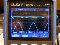
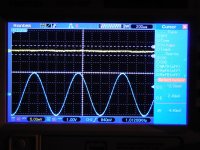
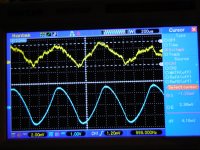
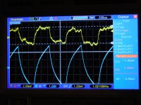
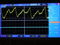
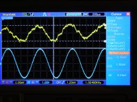
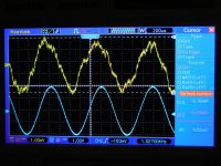
Yes but see the attached screen shots. There's the familiar standard 1KHz sine in Blue Left and the Yellow Right Ghost + with the Blue RCA shorted. Square outputs + Square Left shorted. Triangle outputs + Triangle Left shorted.So the left channel signal is as you would expect due to the RIAA correction and the crosstalk on the right looks like the original uncorrected square wave signal?
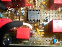
Have you heard of two capacitor bodies "talking" to each other if stood together? I'm thinking of Right input C2 and left output C80A.
And btw, my rendition of the TI OPA 656 circuit to which I added an input buffer and a 3rd-order high pass front-end has the same affliction except in both channels - 5mV and 15mV. I hope the cause of this one is found!
Attachments

I would do the chicken dance if I thought it would help.It is the right time to start with KiCAD.
That is one cute box. If I were younger I'd buy it!Check out how Quant Asylum has done their pcb's with extreme performance.
Yes, I know I've taken up a lot of bandwidth here for this troubling glitch. I truly thought that this circuit could be bread-boarded decently - not necessarily squeaky-clean but at least without this glaring build-issue - if that's what it is. Did you take a really close look? Not that you should but I mean download the Layout and some photos, zoom way in and see if you (or others) can see a trouble area where the Left chan could possibly couple, by any means, into the Right chan's input. But, not the other way around.It makes no sense to build such circuit on a breadboard with random wiring, when one tries to get some good parameters. And then endless posts and descriptions. Wasting time.
The current way of working did not lead to great success so maybe you could consider it. Or just use KiCAD and make things better.I would do the chicken dance if I thought it would help.
With either choice you can only know when actually doing such, not by thinking it won't help.
Last edited:
The channel separation is 59 dB (equivalent to -105 dB of crosstalk from left output to right input at 1 kHz) while the cartridge does 30 dB or so, which is all you need for good stereo imaging anyway, so what are we even talking about? Anyway,
They can capacitively couple, but there should not be much signal voltage across C80A. If C60 were close to C2, that could cause trouble, but it isn't.
One thing you could try as an experiment is to put a grounded shield between the left and right channels. If it doesn't help, it's not capacitive crosstalk.
You could also try temporarily insulating the right channel input RCA connector (or even all the audio connectors) from the case. I don't like it as a solution because it makes the circuit more sensitive to RF fields, but at least it will tell you if there is an issue related to return currents flowing through the case.
Have you heard of two capacitor bodies "talking" to each other if stood together? I'm thinking of Right input C2 and left output C80A.
They can capacitively couple, but there should not be much signal voltage across C80A. If C60 were close to C2, that could cause trouble, but it isn't.
One thing you could try as an experiment is to put a grounded shield between the left and right channels. If it doesn't help, it's not capacitive crosstalk.
You could also try temporarily insulating the right channel input RCA connector (or even all the audio connectors) from the case. I don't like it as a solution because it makes the circuit more sensitive to RF fields, but at least it will tell you if there is an issue related to return currents flowing through the case.
Last edited:
Is it still true that there is no measurable crosstalk with the left output open and the right input terminated with 0 ohm or with 1 kohm, and that "Square.JPG" and "Standard sine + Ghost.JPG" apply with the left output open and the right input open?
If so, then it must be something that injects current into the right channel input. Capacitive crosstalk or board leakage could do so. (Inductive crosstalk would normally induce a voltage and get worse with a low-impedance input termination, and it is unlikely anyway because according to a calculation I just did, you would need a quite big mutual inductance - as long as the left channel output is not shorted.)
With resistive crosstalk from the left output to the right input, the right channel square wave should look more rounded/sine-like than the left channel square wave because of the double RIAA correction. This is contrary to what you measured.
With capacitive crosstalk from the left output to the right input, you would have a cascade of left channel RIAA correction, +20 dB/decade from the capacitive crosstalk (that is, +20 dB/decade up to some ultrasonic frequency where the input capacitance of the amplifier kicks in), right channel RIAA correction. As the RIAA correction on average drops off with less than -20 dB/decade, the result may look a bit more square-wave-like than the signal coming out of the left channel. This is also what you see, although it surprises me how big the measured difference is.
I think everything still points to capacitive crosstalk from the left channel to the input of the right channel. 0.019 pF will do the trick if it is from the left output to the right input. A thin grounded shield between left and right may help. On the bottom side, you could ground some (or all) of the metal strips you don't need.
Sorry, not so. I think I've confused you. From the top:Is it still true that there is no measurable crosstalk with the left output open and the right input terminated with 0 ohm or with 1 kohm, and that "Square.JPG" and "Standard sine + Ghost.JPG" apply with the left output open and the right input open?
I had Left and Right outs connected to the x1 scope, Blue and Yellow, resp. In all cases the Left input was driven by one of three 20mVpp signals with the Right input open, as always. Now, in the Left output I used a "T" connector so I could insert a 0-ohm plug across the Left with the scope still connected. When you see the Left Blue trace go flat that's when the 0-ohm shorting plug is in the T - aka 100ohm R40 taken to Gnd but with U2's output still active.
"Standard sine + Ghost" is just the same old sine wave reference display with; Left driven, Right open, no plugs with the resulting Right Ghost. Whereas "Sine with Left shorted" is shorthand for the same setup but the shorting plug in the T so Left Blue goes flat. And so on. Square or Triangle input with and without "Left shorted". So there are three cases of how the Right output Ghost waveforms look (i.e. differ) with Left output not shorted vs. with it shorted. Just more information.
The squarish look of the square wave Ghost w/out the Left shorted is correct (i.e. Square.jpg). And yes, it doesn't look double-EQed. "Square with Left shorted.jpg" is what happens to the former after shorting plug put into the T. That waveform is mysterious but maybe not to you with the above clarifications.With resistive crosstalk from the left output to the right input, the right channel square wave should look more rounded/sine-like than the left channel square wave because of the double RIAA correction. This is contrary to what you measured.
Take a look at the placement of the Right channel open input C2 / R13 and the albeit grounded end of the Left channel's C80A (same fat Gnd used by R13 and R6 and Right output shield). The C2 and C80A component bodies are practically or are, physically touching. The metal strips they connect into are side-by-side, in-parallel but of course, C80A's strip is grounded.I think everything still points to capacitive crosstalk from the left channel to the input of the right channel. 0.019 pF will do the trick if it is from the left output to the right input. A thin grounded shield between left and right may help. On the bottom side, you could ground some (or all) of the metal strips you don't need.
If you think C2/R13 and C80A are chatting, I could move C80A down one strip and then ground its vacated strip. I have copper tape and have tried a bit at partitioning the R & L halves (i.e. the borderline between C2/R13 and C80A/B). Nothing yet. Yes, I can ground the unused strips. Please take a second look.
Thanks Marcel.
Just saw this earlier post:
Call it a "+1" illness. 😊The channel separation is 59 dB (equivalent to -105 dB of crosstalk from left output to right input at 1 kHz) while the cartridge does 30 dB or so, which is all you need for good stereo imaging anyway, so what are we even talking about? Anyway,
Sorry, not so. I think I've confused you. From the top:
I had Left and Right outs connected to the x1 scope, Blue and Yellow, resp. In all cases the Left input was driven by one of three 20mVpp signals with the Right input open, as always. Now, in the Left output I used a "T" connector so I could insert a 0-ohm plug across the Left with the scope still connected. When you see the Left Blue trace go flat that's when the 0-ohm shorting plug is in the T - aka 100ohm R40 taken to Gnd but with U2's output still active.
There is no confusion. It's what I understood: the left output open and the right input open for "Square.JPG" and "Standard sine + Ghost.JPG", although writing "left output open" was inaccurate, because it was still connected to the scope.
In your earlier experiments, the crosstalk became invisibly small when you put 1 kohm across the right input (with the left output only loaded by the oscilloscope). Is that correct?
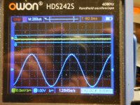
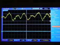
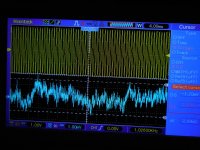
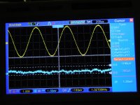
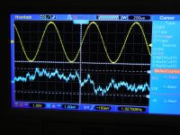
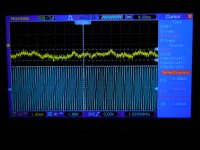
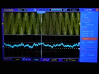
Attached is today's portfolio. Note that the voltage scale is now 1mV/div and as before, Yellow is Right and Blue is Left.In your earlier experiments, the crosstalk became invisibly small when you put 1 kohm across the right input (with the left output only loaded by the oscilloscope). Is that correct?
There are three pics with the usual left chan driven and right ghost with right 1K plug in and no 1K plug. There are also four pics with the right chan driven and left ghost with left 1K plug in and no 1K plug. The big diff here is that when the left is driven with no right plug the ghost we are chasing IS the left's 1KHz signal. However when the the right is driven with or without the left 1K plug there's no real trace of the right's 1KHz signal (i.e. no signal crosstalk - just noise and crapola).
Attachments
-
 Close-up no 1K plug in Left.JPG645.8 KB · Views: 4
 -
 With 1K plug in Left.JPG426.7 KB · Views: 4
 -
 No 1K plug in Left.JPG471 KB · Views: 4
 -
 Close-up with 1K plug in Right.JPG459.2 KB · Views: 4
 -
 With 1K plug in Right.JPG382.7 KB · Views: 3
 -
 No 1K plug in Right.JPG470.7 KB · Views: 4
 -
 Close-up with 1K plug in Left.JPG523 KB · Views: 4
- Home
- Source & Line
- Analogue Source
- OPA1656 Phono Preamp: Split from OPA1656 thread