A 100 nF coupling capacitor between a 600 ohm or so (precise value doesn't matter much) cartridge and a 47 kohm phono amplifier input results in a first-order high-pass filter at 33.4 Hz. It attenuates 5.79 dB at 20 Hz, 16.6 dB at 5 Hz. (124.3 nF would have made it a first-order high-pass at 26.9 Hz, see the next point.)
The servo of post #239 forms a first-order high-pass filter at 26.9 Hz. It attenuates 4.49 dB at 20 Hz, 14.76 dB at 5 Hz.
The circuit of post #234 is an RIAA amplifier with a second-order Butterworth high-pass filter at 13.36 Hz. A second-order Butterworth high-pass at 13.36 Hz attenuates 0.79 dB at 20 Hz, 17.16 dB at 5 Hz.
If it's the bass loss you are concerned about, I don't see how replacing one kind of first-order high-pass filter with another can solve anything. Going higher order will improve it without sacrificing the subsonic suppression.
Last edited:
Sorry if I can't write much and sooner. Yesterday I cut away a slice of my right index finger, very bloody, and it's difficult to typewrite with a fat bandaged finger.
Yes, I understand that going higher order will improve the filter response without sacrificing subsonic suppression, but the FR curves I was getting in my sims didn't look good.
I realize the 2nd order HP you added was Cx and Rx.
I will capture the curves from your mod, with all the right values, for a comparison with the servo moved to the 1st stage. I started adjusting the values from Borbely's original design until I got to the best ones. Let me do all the sims and captures.
Now you are back to first order again. This version and the one with only a servo in the first stage also amplify the second op-amp's offset 50.28 times.
By the way, when CX is present, R9 should be 1740 ohm. That's because CX affects the low-pass filter R9-C3 somewhat.
That sounds quite painful, I hope you recover soon!
By the way, when CX is present, R9 should be 1740 ohm. That's because CX affects the low-pass filter R9-C3 somewhat.
Yesterday I cut away a slice of my right index finger, very bloody, and it's difficult to typewrite with a fat bandaged finger.
That sounds quite painful, I hope you recover soon!
Last edited:
Aren't Cx and Rx a second order filter? An HP series capacitor followed by a resistor to ground?Now you are back to first order again. This version and the one with only a servo in the first stage also amplify the second op-amp's offset 50.28 times.
The servo loop of post #234 and CX and RX together form a second-order high-pass filter. Only CX and RX gives you first order.
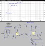
As promised, I have checked how my single op-amp RIAA amplifier with subsonic filter could be changed for a higher cut-off frequency. This is the result, with second- or third-order Butterworth roll-off below 16 Hz:

C5, C6, C8, R8 and R12 need to be accurate to get accurate RIAA correction, the other resistors and capacitors mostly affect the subsonic filter response (and R6 and C4 the cartridge loading).
C5, C6, C8, R8 and R12 need to be accurate to get accurate RIAA correction, the other resistors and capacitors mostly affect the subsonic filter response (and R6 and C4 the cartridge loading).
Last edited:

You can’t get 2nd order with only one reactance. It is 1st order.Aren't Cx and Rx a second order filter?
OK, Marcel, I will modify the Borbely style preamp following your suggestions.
No what about the Walt Jung two-stage passive preamp in
Which is the best way to add a 2nd order HP filter to it as on the active preamp? The servo on the second stage still has to be an option.
No what about the Walt Jung two-stage passive preamp in
Here's the Walt Jung two-stage passive preamp with DC servo, as published by AD here:
https://www.analog.com/media/en/training-seminars/design-handbooks/Op-Amp-Applications/Section6.pdf
https://www.analog.com/media/en/training-seminars/design-handbooks/Op-Amp-Applications/Section6.pdf
Which is the best way to add a 2nd order HP filter to it as on the active preamp? The servo on the second stage still has to be an option.
Meaning the high-pass filter has to work with and without the DC servo loop? Are AC coupling capacitors at the input allowed or forbidden?
Yes, with and without DC Servo loop. To make a listening comparison, if possible.
I don't like input capacitors with such low level signals. Even if they are used on transformerless mic preamplifiers.
I don't like input capacitors with such low level signals. Even if they are used on transformerless mic preamplifiers.
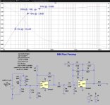
You could try something like this

with
R1 = 10.2 kΩ
C1 = 302 nF
CA = 100 nF
CB = 100 nF
RA = 78.7 kΩ
RB = 174 kΩ
It's combining the passive RIAA network with a second-order Sallen and Key high-pass filter, having a second-order Butterworth response with 13.72 Hz cut-off frequency. I've slightly changed two RIAA correction network values (R1 and C1) because of the loading of the high-pass filter on the RIAA correction network.
You're a genius! Thanks a lot, Marcel! Marvelous job!
Some questions are in order:
1) Can the preamp be used with and without the DC servo? The sims seem to hint so, trying different opamps.
2) The input resistor & capacitor can be the original ones? Grado recommended 47K / 100p as load for my cartridge.
3) My opamp of choice should be the OPA637, which I have a few of. But I intend to try others I have. My only source, from my country, to OPA1656 and 164x is Aliexpress, and they could be fakes. Will try them anyway.
https://www.aliexpress.com/item/100...HQNv62Pv&utparam-url=scene:search|query_from:
4) The OPA164x simulates better than the OPA1656: lower noise and usable low offset. How they compare sound wise for those who tried both?
1) Yes.
2) You can best follow the recommendation from the cartridge manufacturer for the load impedance, and subtract the capacitance of the cable between the cartridge and the amplifier. (If you should run into the kind of problem this thread started with, you may need to add an RC damping circuit, but that's very unlikely because of the flat gain of the first stage.)
3) OPA637 should work very well in this circuit, except as the integrator of the DC servo loop. You need a unity-gain-stable FET op-amp for that.
4) No comment.
My idea is to use the LF411, that I have plenty of, on the servo. It's FET and unity gain stable. Borbely used it until his latest design.
I don't know why it also seems to work well when, for fun, I simmed the 411 for main opamps. When the time comes I plan to listen to it.
All in all, I am getting ready to devise the mods to the existing AE RIAA boards, and start building.
Thanks again Marcel! Your help made the difference. Let's hope others get interested on this project.
It probably won't take long until the Chinese that built these boards might include these mods too.
Just out of curiosity: have you seen the Denoisator thread? You add a small pcb to an existing 3X7 regulator, and it improves things like noise and PSRR. It's what I plan to use here, instead of the board factory regulators.
I will use the LF411, which I have a few of, for the DC servo, which will be on a separate proto pcb board. The one Borbely used on all his discrete preamps.
You might remember that this preamp project will be assembled on two different Aliexpress boards, where I will change the discrete parts of. I will open a threat with all the operating details.
Changing the on-board supplies will be the most laborious work of this all, as I intend to replace the original supplies with the Denoisator supplies developed on another thread of this forum. Look which the regulators will be...
1) Be aware that the opa637 is a 5x gain only op amp. Your schemo from #244 would have U2 going to x1 and crazy,Some questions are in order:
2) If this unknown model # Grado says it needs 100pF max load it's out of luck. The internal wiring of your Thorens is probably at least 100pF from head shell to plinth output. Your cable from there to the preamp is at best, 12-13pF per ft, maybe more. So the recommendation is to remove the 100pf input cap. A lot of big name carts misbehave with = or > 200pF total.
2a) I have been wondering what the purpose is of your R-C / R-C / R network the Grado sees right off the bat at the phono input. What is that there for?
3) Correct. 1x gain OPA627 is called for but hi-$$. Many other choices.
4) If this is a one-off design (i.e. not for production) and if you trust "those who listen" then just stick with the OPA627/637.
Your power supply stimulations seem far too involved for what's necessary, IMHO so good luck debugging all that. But it's your box so have at it.😉
Be aware that the opa637 is a 5x gain only op amp. Your schemo from #244 would have U2 going to x1 and crazy,
Do you mean U1 in post #244, U2 in post #243? For some reason the second op-amp of post #244 is called U1.
If so, good catch! Getting rid of the 56 pF capacitor C5 should solve stability problems.
Last edited:
- Home
- Source & Line
- Analogue Source
- OPA1656 Phono Preamp: Split from OPA1656 thread