Right now we don't have an exact replacement for the LME49990. OPA1611/1612 would be the closes. Although I have to think the noise from the resistors in the difference amplifier stage (after the buffers) in a 3 op amp balanced input would be a larger factor than the op amp noise itself.
Personally, I like to use FET type op amps right at a signal input. They're usually more robust against EMI, and the lower input bias current allows for higher bias current resistors / smaller AC coupling capacitors. This usually results in better CMRR at low frequencies.
Personally, I like to use FET type op amps right at a signal input. They're usually more robust against EMI, and the lower input bias current allows for higher bias current resistors / smaller AC coupling capacitors. This usually results in better CMRR at low frequencies.
An excellent point. So does that mean that, in a flat frequency response circuit, that the low frequency noise spec is insignificant compared to the 1KHz and 10KHz specs?Yep, the JFETs used in the OPA1642 input stage still have an edge over CMOS (1656) for low frequency noise. However, I should point out that broadband noise in most audio applications is way more important. Although we're used to seeing frequency on a log scale, it tends to distort our perception of how much the low frequency noise contributes to the total integrated noise over the audio bandwidth. Just consider, there is 19x more bandwidth between 1kHz and 20kHz than there is between DC and 1kHz.
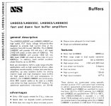
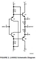
The old National Semiconductor Hybrid LH0002, LH0033 and LH0063(Damn Fast) are wide-band, high current, unity gain buffers often used as part of a compound amplifier to buffer an op amp output.
One issue is they tend to have negative input impedance, so one needed to add a series 50 ohm resistor (or higher resistance) in series with the buffer input. One also needs to pay attention to the additional phase lag of the buffer, when closing the loop with feedback.
LH0024 Application Note 227 Applications of Wide-Band Buffer Amplifiers: https://www.ti.com/lit/pdf/SNOA725A
Those parts are obsolete, but TI has some newer IC variations such as the LMH6321 & BUF634A
https://www.ti.com/product/LMH6321
https://www.ti.com/product/BUF634A
This newer TI app note that mentions the technique: Pairing up Op Amp and Buffer for Higher Output Power Plus Speed in ATE: https://www.ti.com/lit/pdf/sboa357
In 1988 there was a National Semiconductor Hybrid LH4106 which was composed of a cascaded LM6161 opamp and a LH0002 buffer.
Attachments

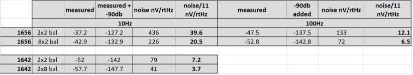
I measured again the noise of OPA1656 vs OPA1642. To check if they will match the previous ones that were made with balanced 10x paralleled op-amps.
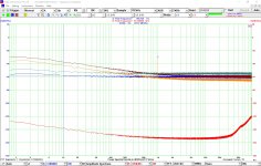
The schematic, spectrum and results are given below. Two schematics in parallel and eight in parallel for both 1656 and 1642 were measured. These combinations should be equal to a single op-amp noise and 4 paralleled op-amps noise. Setup calibrated in dbV. Output signal is amplified 90db. The 1kHz peak at -30db is a -140db control signal injected using 1V RMS generator and 100k/10miliohm divider. 10x@Dicks site for the idea.
blue spectrum - 2 x 8 parallel OPA1642 , green spectrum - 2 x 2 parallel OPA1642
orange spectrum - 2 x 8 parallel OPA1656 , brown spectrum - 2 x 2 parallel OPA1656
Based on these measurements I expect the noise of a single OPA1656 to be 39nV/rtHz at 10Hz.
Attachments

An excellent point. So does that mean that, in a flat frequency response circuit, that the low frequency noise spec is insignificant compared to the 1KHz and 10KHz specs?
Yes, that is usually true. You can prove this to yourself in simulation as well. TINA-TI for example has a "total noise" option which integrates noise over the simulated bandwidth.
Or just change the x-axis to a linear scale to see the true impact of noise at each frequency.
Hi John,
I read the single version of the OPA1656 was under development, do you have any updates about this option?
Thanks for the valuable information you share here!
I read the single version of the OPA1656 was under development, do you have any updates about this option?
Thanks for the valuable information you share here!
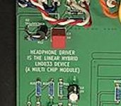
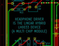
I exhibited & gave listening demonstrations of a headphone amp at the 2019 Burning Amp festival, using a composite topology with the ancient hybrid LH0033 as the output stage. Because they're obsolete and rare and expensive, I socketed the LH0033s. Then I built little "daughter card" LH0033-emulators out of modern production, cheaper parts. During bring-up and testing, the (expendable!) emulator cards were plugged in, so that if anything went wrong, I didn't destroy a hard-to-replace LH0033. Daughter cards are visible in the white ceramic bowl at upper right in the photo.
The headphone amp was called "Azul" and Ti Kan photographed it beautifully:
http://www.tikan.org/ti/audio/burningamp2019/baf2019-19.jpg
Since the LH0033 was socketed, I worried that it couldn't dissipate much heat into the PCB. So I added blue heatsinks, attached to the flat top of the LH0033 packages using phase change thermal interface material. These blue heatsinks are easy to spot in the photo.
Also visible are the gain switching relays (black rectangles amidships) and the input selection & output muting relays (white rectangles along back edge of PCB).
_
Attachments
I can't give specifics here because it's a public forum. But yes, it's on the way. And I will make a post here when it's sample-able on ti.com. You shouldn't have to wait too much longer ;-)
You shouldn't have to wait too much longer ;-)
FANTASTIC!!
Thanks 😉
Is there a quad version coming?
An alternative is the OPA1644 (quad op amp), which may work for many audio applications: https://www.ti.com/product/OPA1644
A quad die takes nearly twice the die area of a dedicated dual die, pad routing rework takes time & typically a quad die uses a common bias generator (more layout rework). One can put two die in a package, but then standard pin out is an issue (unless one adds extra bonds pads on the dual die).
It is a costly proposition to make a quad out of a dual, if the expected customer volume is not there.
Generally, dual op amps sell better than quads, except in the really cheap ICs like the LM324.
Releasing a dedicated quad die reworked from a dual die requires a lot of resources..
Design
Layout
Product engineering
Test Development
Packaging
Qualification/Reliability testing
New Mask set $$
Minimum number of wafer runs (silicon costs) $$
Marketing/Applications
Last edited:
All of the above is true. Dual die quad channel op amps have gotten more popular in recent years to address some of these, but there are definitely drawbacks.
On the OPA1656 quad, the other issue to consider is the power dissipation in the package gets quite high (for op amps). Right now the quad channel version is up in the air, unless someone here could pony up and buy a million of them ;-)
On the OPA1656 quad, the other issue to consider is the power dissipation in the package gets quite high (for op amps). Right now the quad channel version is up in the air, unless someone here could pony up and buy a million of them ;-)
Yep, TI/BurrBrown learned that the hard way when they had to discontinue the OPA2604 dual because at max supply rails (48V!) it heated up so much that it exceeded its input bias current / input offset voltage spec. So now today you can only buy it as a single: OPA604. Which is a real shame because the Pass Labs designed WHAMMY DIY project was *designed for OPA2604*. Now they gotta use other, crappier, DIP8 duals.
The exception is phono preamps. Because the RIAA eq curve has highest gain at low frequencies, 1/f noise matters. And on MM phono preamps, the cartridge inductance is high enough that amplifier current noise may also matter. I like phono preamps because you can't ignore any noise contributors like you can in other circuits!
1/f noise isn't even that critical for phono preamplifiers when you take A- or ITU-R-weighting into account. Below 1 kHz, the A-weighting curve drops faster with decreasing frequency than the RIAA curve rises. With IEC-modified RIAA- and A-weighting, the break even point is around 1169 Hz: a given amount of voltage noise at 1169 Hz leads to the same integrated weighted noise no matter whether the noise is white, 1/f or a combination of both.
Totally agree. I just was trying to avoid the a-weighting side of the argument since sometimes that can lead to arguments on whether it's a true reflection of audibility. I didn't want people to think I was using a-weighting as a cop out 😀
Funny how carefully the data sheet stays silent if it is MOSFET or JFET.
Don't you repel a customer!
And then those PSSR measurements to 5 GHz. Numbers to impress
the simple-minded. As if 20 pF would not take care of that.
Gerhard (RF guy)
Don't you repel a customer!
And then those PSSR measurements to 5 GHz. Numbers to impress
the simple-minded. As if 20 pF would not take care of that.
Gerhard (RF guy)
Well, you can figure out if it's JFET or CMOS from the data. I would argue that if we get to the point where you can no longer tell, then it's not an important distinction 🙂.
The OPA2156 datasheet says CMOS, though. Maybe they just don't want to deal with audiophile biases.
The OPA2156 datasheet says CMOS, though. Maybe they just don't want to deal with audiophile biases.
Last edited:
Funny how carefully the data sheet stays silent if it is MOSFET or JFET........And then those PSSR measurements to 5 GHz. Numbers to impress
the simple-minded. As if 20 pF would not take care of that....
The data sheet is often created by the Applications/Marketing group. Sometimes things get left out if the person approving the final document does not consider the detail important.
On the MOSFET input, the only RF rectifying junction on the input should be the ESD diodes. BJT inputs have the RF rectifying junction on the input device. Radiated EMI susceptibility can also be an unexpected problem (plastic package).
Customers often have issues with EMI susceptibility on general purpose op amps.
app note...EMI Rejection Ratio of Operational Amplifiers: https://www.ti.com/lit/pdf/sboa128
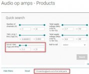
Searching on ultra low noise (default search on voltage noise) audio amps on the TI.com website, it reduces the op amp list very quickly to only a few: https://www.ti.com/amplifier-circuit/op-amps/audio/products.html#p7typ=1.1;3
There is a downloadable op amp software selection tool: https://www.ti.com/tool/OPAMPS-SELGUIDE
Attachments
On the OPA1656 quad, the other issue to consider is the power dissipation in the package gets quite high (for op amps).
Happens with duals too... A less than happy TI story happened a few years ago, multiple customers complained about the popular (for audio) OPA2604 dual op amp, marred from multiple issues (running very hot, out of spec parameters, serious drifts in offset, etc... to a complete failure) when powered to the full extend of the supply spec (+/-24V, which was one of the reasons for its "audio" popularity). TI danced around the issue, the supply pipe was strangled (you could not buy the OPA2604 from the distributors without agreeing to, and signing a TI disclaimer). Then they completely dumped the part from their catalogue. The single version, OPA604, survived and is still an excellent part for audio, still with no match in the max supply voltage of 48V.
P.S. Just noted Mark's comment a few posts up. Same story.
Last edited:
- Home
- Vendor's Bazaar
- OPA1656: High-Performance CMOS Audio Op Amp