I am trying to build one. it shouldn't be more complicated, especially if you forgo the current-sensing resistor. the datasheet I believe has both inverting and non-inverting designs.
I am adopting the inverting design, using the same resistors / caps from my lm3875 gainclone.
I am adopting the inverting design, using the same resistors / caps from my lm3875 gainclone.
im using the OPA541 and OPA549
my website is:
http://www.freewebs.com/matttcatttweb/index.htm
also i found this ages ago:
http://diyaudio.com/forums/showthread.php?s=&threadid=11931&highlight=opa541
my website is:
http://www.freewebs.com/matttcatttweb/index.htm
also i found this ages ago:
http://diyaudio.com/forums/showthread.php?s=&threadid=11931&highlight=opa541
I also prefer the opa541. Have you seen (in real life) the opa541am? That's one juicy op😎
see also http://diyaudio.com/forums/showthread.php?postid=198891#post198891
http://www-s.ti.com/sc/psheets/sboa057/sboa057.pdf
maybe
http://www-s.ti.com/sc/psheets/sboa037/sboa037.pdf
and
http://www-s.ti.com/sc/psheets/sboa020/sboa020.pdf
and
http://www-s.ti.com/sc/psheets/sboa082/sboa082.pdf
😉
see also http://diyaudio.com/forums/showthread.php?postid=198891#post198891
http://www-s.ti.com/sc/psheets/sboa057/sboa057.pdf
maybe
http://www-s.ti.com/sc/psheets/sboa037/sboa037.pdf
and
http://www-s.ti.com/sc/psheets/sboa020/sboa020.pdf
and
http://www-s.ti.com/sc/psheets/sboa082/sboa082.pdf
😉
I managed to build a test circuit for the OPA 541 and used parts I had at hand.
At the input I have a 100k clarostat pot feeding a MKP 1.5uf poly cap. From there on I have a 10k metal film on the inverting input with a 220k metal film for the feedback network.
For the power supply I chose to use the 2 Elna 15 000uf caps bypassed with some Philips 0.1uf poly caps....I`m getting a solid 26vdc out from this setup.
So far I have just injected a 1000hz sine wave at 2v into the input and things sound ok. I chose to use the current clamping resistor as I had a nice 0.1ohm 1% 15 watt metal film resistor handy and wanted to be safe.
I havent made any crucial measurements yet as I let it run over night........I`ll post my results when I do.........I`m going to interested in comparing the 3886 I have yet to build.
Cheers!!The DIRT®

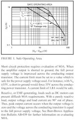
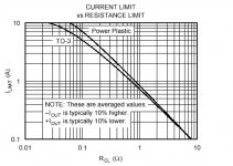
Here we see what Rcl to use after having studied the SOA:
Seems I also read the datasheet a little too fast before, as I adviced someone to use 0R1/0R15 with the opa541 am/ap respectively. Consulting the SOA chart and the graph below we see that with 35V rails we have to use 0R4 to be safe (1,8A limit)...
edit:
(Note that I'm not using any resistor at all in mine, nor does MatttCattt either I believe) -We're "fearless DIY'ers". 😉
This makes you think about the other chips, with pre-programmed protection (eg LM3875), and how safe they really are. I've read several places about people having fried their chips with shorted outputs/other nasty habbits. After all, why should we bother with CL in a chip, whilst we don't with the other (discrete) amplifiers we build? I say; leave it out, enjoy the fat sound, and don't do nasty things to your amps! 😉
Attachments
millwood said:
I am adopting the inverting design, using the same resistors / caps from my lm3875 gainclone.
How's that going? Have you had the chance to compare the sound yet?
Mad_K said:(Note that I'm not using any resistor at all in mine, nor does MatttCattt either I believe) -We're "fearless DIY'ers". 😉
fearless diyers? im just to ignorant to know that i shouldnt 😛 😉
Mad_K said:
How's that going? Have you had the chance to compare the sound yet?
not yet. I am still in the planning stage, 🙂
I`m not to concerned about the cl resistor right now. I have just used one for testing and have a very light load on it.
I was testing more for any noise on the layout as I chose to p2p wire it
I was testing more for any noise on the layout as I chose to p2p wire it
Do they need to be matched?
Hi, guys.
I have a Noob question: I've just purchased a couple pairs of OPA541 and I'm wondering if they need to be matched as pairs the same way individual FETs do?
I kind of figured that the variances in performance of an OpAmp from one chip to another would be minimized by design, but I really don't know.
Thanks
-Erik.
Re: Do they need to be matched?
Dont need to much them if your design isn't too much "cutting edge".
e.lectronick said:Hi, guys.
I have a Noob question: I've just purchased a couple pairs of OPA541 and I'm wondering if they need to be matched as pairs the same way individual FETs do?
I kind of figured that the variances in performance of an OpAmp from one chip to another would be minimized by design, but I really don't know.
Thanks
-Erik.
Dont need to much them if your design isn't too much "cutting edge".
Re: Re: Do they need to be matched?
no need for matching, but I think it's nice to use chips with the same lot code (printed on the chip) 😉
GregGC said:
Dont need to much them if your design isn't too much "cutting edge".
no need for matching, but I think it's nice to use chips with the same lot code (printed on the chip) 😉
- Status
- Not open for further replies.
- Home
- Amplifiers
- Chip Amps
- opa 541 question