You might like to have a look at the link below:What is your opinion on decoupling capacitors between the positive and the negative rail?
opamps and local decoupling of rails, some questions
Regards,
Braca
Illinois capacitors used to do very high quality and reliable industrial capacitors...i don't really know were your doubts come from...i think the ones i have from them and the Siemens(epcos) ones are the only ones i saw to speciffy the Ieff max value on them...
I agree with you. The only thing I have said is Illinois Capacitor as well as ALL companies who cannot be considered of extremely large size are not trustworthy and their specifications cannot be trusted. I gave an example for trustworthy companies : Analog Devices and Texas Instruments. Anything of lower size may not be considered trustworthy.
In regards to Illinois Capacitor, I am happy you have posted a positive review. This makes them slightly more trustworthy. However, they have discontinued their Ceramic capacitor line. They do not make them anymore.
Thanks for your positive opinion. Hopefully, they will restart production or will sell their line to another manufacturer.
Illinois capacitors used to do very high quality and reliable industrial capacitors...i don't really know were your doubts come from...i think the ones i have from them and the Siemens(epcos) ones are the only ones i saw to speciffy the Ieff max value on them...
Can you, please, post the type of Siemens capacitors you have mentioned. Can you post a link to their, respective, web page.
You might like to have a look at the link below:
opamps and local decoupling of rails, some questions
Regards,
Braca
I know people like to add tiny output resistances on power supply. I disagree. I want a power supply with as low output impedance as possible. In this sense, the tracks should be wider than necessary and straight. The capacitors should be able to do the job.
I have tried to summarise this thread. Hopefully, I have not forgotten many of the discussed things. Here is the summary :
Summary :
1. Normal Capacitor Decoupling
The most important reasons for amplifier IC decoupling are the impedance of the tracks and the noise from the load ( the load is from output to ground and, therefore, through each of the output transistors, from a given power supply rail, the positive or the negative, to ground, fully differential amplifiers are an exception ). Temporary power can be provided by decoupling capacitors, from each rail to ground, as close to the power supply pins. The ground plate ( in case any ) can be used to connect the capacitors to, usually, by vias. There is no need for a capacitor between the rails ( between positive and negative ) in order to keep the noise even lower.
The size and type of the capacitors ( as well as the connections, i. e., from rails to ground only ) is, usually, specified by the manufacturer in the datasheet. The manufacturer suggested decoupling is the best. Hopefully, they do not want to save capacitors in order to advertise their products as such, which do not require components.
In case, the manufacturer does not specify the capacitive decoupling, 0.1uF X7R can be used.
2. Crazy Capacitor Decoupling
In addition to the Normal Capacitor Decoupling, more capacitors can be used in parallel, such as 1uF, X7R, additional 10uF, 10nF, 1nf, 100pF and 10pF can be used, as many of these as available better be X7R. In addition, > = 10uF Tantalum and > = 10uF electrolytic, audio, Nichikon can be used. All capacitors must be with as low ESR and ESL as available for the respective kind.
The amplifier may be looked at a differential load : from positive to negative rail, which, may also be used for high frequencies. Thus, similar chain of paralleled capacitors may be used between the two rails at the expense of some, hopefully, tiny or negligible noise.
Note : no amplifier manufacturer is known to have ever specified the use of decoupling capacitors between the positive and the negative rail in their documentation. ( Fully differential amplifiers may be an exception ).
Last edited:
I have seen capacitors between the rails in one or two old datasheets I am pretty sure.
I would also say that #2 is not a good idea. You will get anti-resonant peaks and you are forming a complex network. Unless you own a VNA and plan to take the pains to measure it in-circuit, it's a guessing game.
There are virtually *no* applications where extremely low value decoupling capacitors are useful anymore. Maybe in RF circuits or extreme high speed PLLs or clock buffers. The impedance of a modern MLCC is basically defined by its mounted inductance, which is dominated by package and layout. Values below 0.1uF were useful when you couldn't get larger values in small or low inductance packages. Nowadays, you can get huge caps in 0402 or larger. The largest capacitor in the lowest inductance / smallest package you can select is often the better choice. If you need lower impedance, then parallel the same value. Below: Z of 0805 MLCCs from the same series.

Tossing in random pF caps is going to do nothing but add to your BOM cost unless you are explicitly trying to provide low impedance at cellular frequencies or something, and then you still need to test and measure.
I would also say that #2 is not a good idea. You will get anti-resonant peaks and you are forming a complex network. Unless you own a VNA and plan to take the pains to measure it in-circuit, it's a guessing game.
There are virtually *no* applications where extremely low value decoupling capacitors are useful anymore. Maybe in RF circuits or extreme high speed PLLs or clock buffers. The impedance of a modern MLCC is basically defined by its mounted inductance, which is dominated by package and layout. Values below 0.1uF were useful when you couldn't get larger values in small or low inductance packages. Nowadays, you can get huge caps in 0402 or larger. The largest capacitor in the lowest inductance / smallest package you can select is often the better choice. If you need lower impedance, then parallel the same value. Below: Z of 0805 MLCCs from the same series.
Tossing in random pF caps is going to do nothing but add to your BOM cost unless you are explicitly trying to provide low impedance at cellular frequencies or something, and then you still need to test and measure.
Last edited:
As mentioned, some manufacturers specify 1uF as the capacitance with the lowest ESR and Z. I think, TDK were one of these.
Low value capacitors may not help, true, unless they have low ESR's and Z at high frequencies and may help at high frequencies.
Paralleling capacitors, in general, may help as the ESR's are also, somewhat, in parallel, though not directly.
Low value capacitors may not help, true, unless they have low ESR's and Z at high frequencies and may help at high frequencies.
Paralleling capacitors, in general, may help as the ESR's are also, somewhat, in parallel, though not directly.

Paralleled bypass caps.
Chris,
I look at your impedance plots and get a different take. For example, 2.2uF || 0.1uF would detune the single frequency resonance, and extend impedance below 0.1ohm from a limited 1MHz/10Mhz range to a much wider 1 MHz/50 Mhz range, and halve all impedance above 50 MHz. Just because the impedance curve becomes more complicated does not mean it is worse.
Lots of op amps in audio use these days have GBW of 100 MHz or higher. The bypass cap impedance should stay low until it is above the GBW frequency. It is important to use bypass caps appropriate for the op amp you are using, not the signals you are putting in. I'd argue for using multiple SMD package sizes, but package inductance will be swamped by layout inductance, so that's moot. Bypass caps should basically be on the supply pins directly to a large GND plane.
Single-sided boards can have a difficult time with bypassing. Excessive length of GND traces to the op amp can cause excessive inductance, which causes a ringing LC circuit. This has to be damped. Some will use caps with higher ESR, which damps the ringing, but causes poor bypass. Some will put an R in series with the supply rail, which is probably the better fix. Steven disagrees. It's a bandaid for bad layout, so he's right that is should not be used. Sometimes it is necessary, however.
With a two layer board, the bottom side should have as much GND plane as possible, but that is not always easy, so even two layer boards can have ringing on the bypass caps, due to excessive inductance on VCC, VEE, and GND routing.
--Russell
I would also say that #2 is not a good idea. You will get anti-resonant peaks and you are forming a complex network. Unless you own a VNA and plan to take the pains to measure it in-circuit, it's a guessing game.
There are virtually *no* applications where extremely low value decoupling capacitors are useful anymore. Maybe in RF circuits or extreme high speed PLLs or clock buffers. The impedance of a modern MLCC is basically defined by its mounted inductance, which is dominated by package and layout. Values below 0.1uF were useful when you couldn't get larger values in small or low inductance packages. Nowadays, you can get huge caps in 0402 or larger. The largest capacitor in the lowest inductance / smallest package you can select is often the better choice. If you need lower impedance, then parallel the same value. Below: Z of 0805 MLCCs from the same series.
Tossing in random pF caps is going to do nothing but add to your BOM cost unless you are explicitly trying to provide low impedance at cellular frequencies or something, and then you still need to test and measure.
Chris,
I look at your impedance plots and get a different take. For example, 2.2uF || 0.1uF would detune the single frequency resonance, and extend impedance below 0.1ohm from a limited 1MHz/10Mhz range to a much wider 1 MHz/50 Mhz range, and halve all impedance above 50 MHz. Just because the impedance curve becomes more complicated does not mean it is worse.
Lots of op amps in audio use these days have GBW of 100 MHz or higher. The bypass cap impedance should stay low until it is above the GBW frequency. It is important to use bypass caps appropriate for the op amp you are using, not the signals you are putting in. I'd argue for using multiple SMD package sizes, but package inductance will be swamped by layout inductance, so that's moot. Bypass caps should basically be on the supply pins directly to a large GND plane.
Single-sided boards can have a difficult time with bypassing. Excessive length of GND traces to the op amp can cause excessive inductance, which causes a ringing LC circuit. This has to be damped. Some will use caps with higher ESR, which damps the ringing, but causes poor bypass. Some will put an R in series with the supply rail, which is probably the better fix. Steven disagrees. It's a bandaid for bad layout, so he's right that is should not be used. Sometimes it is necessary, however.
With a two layer board, the bottom side should have as much GND plane as possible, but that is not always easy, so even two layer boards can have ringing on the bypass caps, due to excessive inductance on VCC, VEE, and GND routing.
--Russell
The practice of rail-rail decoupling only or avoiding local decoupling altogether (aside from 100 nF or smaller) stems from the days when power and signal grounds would be shared and return resistance alone could be far from negligible. (Lots of constructions would use multiple single-layer PCBs joined together by connectors, for example - from the 1970s well into the late '90s at least.)
Under these circumstances, power supply source impedance, decoupling capacitors and ground return impedance will form a complex voltage divider with a highpass filter characteristic. Effectively, highpass-filtered power supply noise is added to the signal much like you would see with a ground loop. The magnitude of this effect easily degrades effective PSRR below what you would expect from circuit performance once local rail decoupling gets into the double-digit µF.
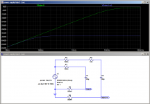
Under these circumstances, adding extra series resistance markedly reduces the problem, even if it does introduce the possibility of crosstalk between circuits if inherent circuit PSRR is modest. A simulation to play around with is attached. (If 500 mOhm of shared ground return seems excessive, try 100 mOhm.)
Much of classic audio engineering revolves around dealing with things like these.
It should come as no surprise, perhaps, that some classic audio equipment can be quietened down substantially by reworking and reinforcing the grounding. In the past I had a bit of an oopsie when the introduction of local RC filtering to get native circuit PSRR up (which had been very low stock) resulted in injecting too much power supply noise, and a dedicated power ground return was needed to fix the issue.
Under these circumstances, power supply source impedance, decoupling capacitors and ground return impedance will form a complex voltage divider with a highpass filter characteristic. Effectively, highpass-filtered power supply noise is added to the signal much like you would see with a ground loop. The magnitude of this effect easily degrades effective PSRR below what you would expect from circuit performance once local rail decoupling gets into the double-digit µF.
Under these circumstances, adding extra series resistance markedly reduces the problem, even if it does introduce the possibility of crosstalk between circuits if inherent circuit PSRR is modest. A simulation to play around with is attached. (If 500 mOhm of shared ground return seems excessive, try 100 mOhm.)
Much of classic audio engineering revolves around dealing with things like these.
It should come as no surprise, perhaps, that some classic audio equipment can be quietened down substantially by reworking and reinforcing the grounding. In the past I had a bit of an oopsie when the introduction of local RC filtering to get native circuit PSRR up (which had been very low stock) resulted in injecting too much power supply noise, and a dedicated power ground return was needed to fix the issue.
Attachments
Last edited:
A cap from rail to rail is pretty useless. Why?
When the opamp output swings positiv the current flows from the +cap through the op into the output pin and then at the next stage through a resistor or cap to gnd.
Then this current also flows from the -cap to the power supply caps to gnd and back to the load resistor.
when the out is negative the same happens with the opposite rail.
so our "decoupling" cap is in series with the big electrolyte and 2x the track length to the supply.
That is such a high impedance that no current at all will flow through it or very little, because then it is much lower impedance to flow direct through the rail to the supply.
You just cannot only look at where the current comes from but also where it flows back it is a closed circle.
now check where this current flows with two caps to gnd
only through the cap and then to the load resistor gnd much lower impedance
Last edited:
Many classic audio op amp circuits are floating. The AC signal only references ground at the input. Active tone controls are an example. The only ground goes to the + input of the opamp and you want it to be a quiet ground. Capacitors to the rail can and will inject local noise into the ground.
For stability, you need to have a low impedance at high frequencies between the power supply pins. A single 0.1 uF high Q ceramic capacitor accomplishes this. Connecting one from each leg to ground will increase the impedance between the pins, as well as risk introducing noise locally into the ground. It is both counterproductive and detrimental to circuit performance.
The local electrolytic bypass capacitor(s) are different. If the circuit is floating, referencing ground only for DC bias, then use one electrolytic capacitor between the supply pins. If the circuit drives a ground referenced load (like a headphone amplifier or line level output) then use an electrolytic capacitor from each pin to ground. Use a separate "dirty" ground for this.
That's what I've always done, and it's always worked for me.
Can't argue a highly technical argument but I have had very good experience putting a stacked film (low inductance) cap directedly across the power supply pins of op amps with the leads as short as possible. Across the top of the chip.
As the op amps have no ground pin or reference coming in, making sure the voltage between the supply pins is clean seems to help a fair amount. Especially with the LM6172 type op amps. (High bandwidth)
YMMV,
Greg
As the op amps have no ground pin or reference coming in, making sure the voltage between the supply pins is clean seems to help a fair amount. Especially with the LM6172 type op amps. (High bandwidth)
YMMV,
Greg
Just because the impedance curve becomes more complicated does not mean it is worse.
It usually is, because we are looking at curves of the capacitor impedance only, not mounted. Add pads and vias (hopefully not traces) and the picture becomes less clear. Two of the same value will bring the impedance below adding the 0.1uF. Just because you are on the "inductive" side of the curve does not mean the cap stops working.
It's hard to really do a proper layout for anything high speed in 2 layers.
Last edited:
That's what I've always done, and it's always worked for me.
That's not exactly evidence that it is best practice.
I have looked at hundreds of datasheets and note that manufacturers do not recommend rail-to-rail decoupling on any high speed devices. I just used a 900 MHz GBW op-amp with no cap between the rails. The eval boards and datasheet do not recommend this either. A low impedance to ground on both rails is de-facto a low impedance between the rails.
If it's a seriously high speed OpAmp, go to 4 or even more PCB layers and make use of distributed capacitance between power and ground planes. Obviously also go full SMD, preferably 0603 rather than 0805 passives. I personally like a Signal-GND-Power-GND stackup with a split powerplane for high-ish speed designs.
Edit: I also often put vias directly in pads, because for hand assembly solder wicking through the via is not really an issue.
Edit2: Chris, I think I have seen such a recommendation in some ADSL line driver datasheets when differential loads are driven. But don't remember which one it was.
Edit: I also often put vias directly in pads, because for hand assembly solder wicking through the via is not really an issue.
Edit2: Chris, I think I have seen such a recommendation in some ADSL line driver datasheets when differential loads are driven. But don't remember which one it was.
Last edited:
I don't do via in pad unless it's filled and plated over. Prefer to do vias touching the pad on the sides since I mostly use a stencil, paste, and oven.
I only picked 0805 because that's the image I found 🙂.
I only picked 0805 because that's the image I found 🙂.
I was considering buying a small infrared oven from China, but then visited a German electronics forum where the list of "strongly recommended modifications" was intimidatingly long. So a DIY-heatplate and a hot air station it is. If it's clear parts of the board will be assembled by reflow, that obviously has to be taken into account when doing the layout.
It's not that I don't want a reflow oven or couldn't use one, but it's very far back on the list of priorities. The lack of reflow oven I can compensate for by soldering skills and manual labor, the lack of instruments on my testbench however not so much. The used older instruments I could afford are too big for my bench, the new compact instruments way out of my budget. Jackpot 😉
It's not that I don't want a reflow oven or couldn't use one, but it's very far back on the list of priorities. The lack of reflow oven I can compensate for by soldering skills and manual labor, the lack of instruments on my testbench however not so much. The used older instruments I could afford are too big for my bench, the new compact instruments way out of my budget. Jackpot 😉
I am thinking that the best advice regarding decoupling comes from two VERY well-respected members of our diy audio community:
From Rod Elliot: Coupling Capacitors
"High speed opamps must have good bypassing. Most of the time, this will be between the power supplies, avoiding the earth (ground) circuit completely. A normal opamp has no knowledge of earth, ground planes or anything else earth related. It is only interested in the voltages present at its two inputs, and when used in linear mode will attempt to make them the same voltage."
And from Douglass Self: http://www.eetimes.com/document.asp?doc_id=1278963
"The essential requirement is that the positive and negative rails should be decoupled with a 100 nF capacitor between them, at a distance of not more than a few millimeters from the op-amp; normally one such capacitor is fitted per package as close to it as possible.
It is not necessary, and often not desirable, to have two capacitors going to ground; every capacitor between a supply rail and ground carries the risk of injecting rail noise into the ground."
Between them, these guys have FORGOTTEN more about audio electronics than the rest of the yahoos on this thread have ever LEARNED.
- Home
- Source & Line
- Analog Line Level
- Op-amp decoupling - best practice?