I also looked up how to test a transistor, and used this test with my DMM set to Ohms.
Connecting the negative probe to the Base pin and positive probe to the collector I measured 5 MOhm. When I measured from Base to Emitter it was also 5 MOhm.
At this point I can despised the resistor and test it. I don’t have a good capacitor tester.
Connecting the negative probe to the Base pin and positive probe to the collector I measured 5 MOhm. When I measured from Base to Emitter it was also 5 MOhm.
At this point I can despised the resistor and test it. I don’t have a good capacitor tester.
Ok I removed Q903.
I now measure:
Across R907 and C916
-1.16 V
-39.1 V
If you look at the circuit those two parts are in parallel and so should have the same voltage across each.
Lets busk it...
With transistor removed lift one end of the Zener to isolate it. If you now see -40 volts on each end of R907 then the Zener is duff. If the voltage doesn't come up remove both caps, C917 and C916. The voltage has to now come up on R907.
If the Zener is duff you must replace the transistor. Lots of common types will be fine here.
Connecting the negative probe to the Base pin and positive probe to the collector I measured 5 MOhm. When I measured from Base to Emitter it was also 5 MOhm.
For a PNP transistor like this you put your meter on Diode range and put the black lead on the base. You should read about '0.600' with the red lead on the emitter and with the red lead on the base. Reverse the leads and the meter should show 'open' which what you see with the leads not connected.
There should be no reading with the red lead on the emitter and the black on the collector.
Those are just basic checks and leave a lot untested but they do cover many failure modes.

Yep, I expected the same voltage on C916 and R907 so I was just double checking.If you look at the circuit those two parts are in parallel and so should have the same voltage across each.
View attachment 1235474
Lets busk it...
With transistor removed lift one end of the Zener to isolate it. If you now see -40 volts on each end of R907 then the Zener is duff. If the voltage doesn't come up remove both caps, C917 and C916. The voltage has to now come up on R907.
If the Zener is duff you must replace the transistor. Lots of common types will be fine here.
I will try desoldering one end of the Zener diode and see what happens. I went ahead and ordered replacement transistors and the C916 capacitor. I have some other for C917.
Is the Zener diode 27V? The part number didn’t show up anywhere, I’m assuming it’s an Onkyo part number.
Thanks again!
The Zener is a common part and not very critical. It will be a 27 volt type with a low power rating.
BZX79 C27
BZV85 C27
Any small 27 volt is fine.
It will be interesting to see.
Early on I think I mentioned I suspected the diagram looked a bit odd... it would work as drawn but it looks incorrectly configured to me.
This is how I would configure it.

BZX79 C27
BZV85 C27
Any small 27 volt is fine.
I will try desoldering one end of the Zener diode and see what happens.
It will be interesting to see.
Early on I think I mentioned I suspected the diagram looked a bit odd... it would work as drawn but it looks incorrectly configured to me.
This is how I would configure it.
Alright I removed one end of the Zener diode and now get -38.8V on both ends of R707.If you look at the circuit those two parts are in parallel and so should have the same voltage across each.
View attachment 1235474
Lets busk it...
With transistor removed lift one end of the Zener to isolate it. If you now see -40 volts on each end of R907 then the Zener is duff. If the voltage doesn't come up remove both caps, C917 and C916. The voltage has to now come up on R907.
If the Zener is duff you must replace the transistor. Lots of common types will be fine here.
I have some transistors and Zener Diodes on the way that should be here today.
I see the part number for the Transistor (2SA10105-GR) and found one in a multi pack.
But I can’t find the Zener diode info. Is the part number 05AZ27R? Is that a 27V Zener Diode?
Thanks,
Ian
OK, I have a 27 V Zener Diode in the pack coming.The Zener is a common part and not very critical. It will be a 27 volt type with a low power rating.
BZX79 C27
BZV85 C27
Any small 27 volt is fine.
It will be interesting to see.
Early on I think I mentioned I suspected the diagram looked a bit odd... it would work as drawn but it looks incorrectly configured to me.
This is how I would configure it.
View attachment 1235480
I'm looking forward to putting in the new components and seeing what happens!
That (with the transistor removed) proves the Zener is pulling the voltage down (duff). It also proves the cap across the Zener is OK. We know you bridged the 10k so it not that.Alright I removed one end of the Zener diode and now get -38.8V on both ends of R707.
So the Zener look duff from here, the big question is did it just fail or was it pushed 😉
It is possible the transistor has some intermittent issue that caused the Zener to fail such as it conducting from Collector to Base. That is why the transistor has to be replaced as well. Its not worth risking as a possible issue in future.
But I can’t find the Zener diode info. Is the part number 05AZ27R? Is that a 27V Zener Diode?
They are very generic, its like you trying to find the fuses specified in the manual... you just fit one of the correct ratings. Zener's can be 'added' in series so a 15v and 12 volt can be wired in series to give a 27 volt.
So the 27 in the part number 05AZ27R is the voltage drop? Is there any way to read that part number of is it proprietary?
I will try the diode test on the transistor I removed.
But I am looking forward to replacing the diode and transistor.
This has been super fun, you guys are awesome. Thanks for being patient with me.
My dad was an electrical engineer but he never taught me any of this stuff, and I didn’t get past a basic EECS class as a mechanical engineer. My dad now has dementia and can barely remember my kids, but he still remembers stuff from years ago. This gives me something to talk about with him and he perks up.
It's a bit academic with a new part in route, but you can try diode test on the zener. If you get similar odd readings in both directions, definitely a bad diode. A good zener would look like an ordinary diode since your meter can't test its reverse voltage.
My dad was an electrician, very smart, but suffered Alzheimer's also. He eventually thought I was his older brother. I know your pain and am apprehensive about my own fate. I'm 76 and feel the Bell curve all around me.
Best.
My dad was an electrician, very smart, but suffered Alzheimer's also. He eventually thought I was his older brother. I know your pain and am apprehensive about my own fate. I'm 76 and feel the Bell curve all around me.
Best.
It will be but its only by knowing in the first place that it is a Zener that I would relate the 27 to voltage. If you just showed me the number I wouldn't have a clue what it was. Looking at the circuit and you can tell immediately what the voltage would be from the regulated -26 volt output. The base emitter junction drops around 0.6 volts and so a 27 volt Zener (if it were exactly that) would give 26.4 volts output. All negative values in your case.So the 27 in the part number 05AZ27R is the voltage drop? Is there any way to read that part number of is it proprietary?
We know the current in the Zener can not exceed a current determined by the 10k and the raw supply and so we get -39 (raw supply) less the Zener value which gives 13 volts and that in turn gives just 1.3 milliamp. The Zener dissipation is current multiplied by voltage and so we get 34 milliwatts. So our Zener really should be the lowest wattage we can obtain (for best performance).
The current taken by the base of the transistor is subtracted from the Zener current but this will be very low in practice in this application.
It should read like an ordinary diode one way (around 0.600 give or take on the diode range) and essentially open the other way.I will try the diode test on the transistor I removed.
(your meter on diode range is actually showing the voltage at the meter terminals as a small test current is passed through the device under test)
Sorry to hear about your dad but its nice he remembers the older stuff.My dad was an electrical engineer but he never taught me any of this stuff, and I didn’t get past a basic EECS class as a mechanical engineer. My dad now has dementia and can barely remember my kids, but he still remembers stuff from years ago. This gives me something to talk about with him and he perks up.
I just tried this on the old transistor and it did what you said. It read 0.7.V but close enough. The replacement reads the same.For a PNP transistor like this you put your meter on Diode range and put the black lead on the base. You should read about '0.600' with the red lead on the emitter and with the red lead on the base. Reverse the leads and the meter should show 'open' which what you see with the leads not connected.
There should be no reading with the red lead on the emitter and the black on the collector.
Those are just basic checks and leave a lot untested but they do cover many failure modes.
And the bad Zener diode read 0.182V in both directions.
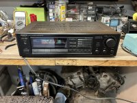
Let me install the new parts
Ok it’s back together. I will have to wait until tonight to hook it up. Off to my next project, pushing the Alfa racecar into the garage so we can diagnose the horrible noise it started making.
I will post a wrap up tomorrow. But thank you to all who helped and were patient with this rookie! I learned a ton. And this is how I learn best, by diving in. Sometimes to my detriment.
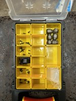
But at least I’m more organized these days. I actually saved the screws from each step in order.
I will post a wrap up tomorrow. But thank you to all who helped and were patient with this rookie! I learned a ton. And this is how I learn best, by diving in. Sometimes to my detriment.
But at least I’m more organized these days. I actually saved the screws from each step in order.
Attachments
Excellent news 👍
As duff as they come 🙂
The 0.6 volts is a typical value I grew up with so don't worry over small differences. It depends a little on the actual manufacturing processes and also the test current and temperature of the device. Old (as in old manufacturing processes) tend to be a bit lower in my experience, sometimes even in the 0.5v region.
For curiosity I just searched 'forward volt drop of silicon diode' and the very first hit is WRONG WRONG WRONG in some of its info. Germanium (very old, the first transistors were germanium) most definitely isn't 0.7 volt, its nearer 0.15 volts. If you ever check LED's then the volt drop on those depends on colour.

And the bad Zener diode read 0.182V in both directions.
As duff as they come 🙂
I just tried this on the old transistor and it did what you said. It read 0.7.V but close enough. The replacement reads the same.
The 0.6 volts is a typical value I grew up with so don't worry over small differences. It depends a little on the actual manufacturing processes and also the test current and temperature of the device. Old (as in old manufacturing processes) tend to be a bit lower in my experience, sometimes even in the 0.5v region.
For curiosity I just searched 'forward volt drop of silicon diode' and the very first hit is WRONG WRONG WRONG in some of its info. Germanium (very old, the first transistors were germanium) most definitely isn't 0.7 volt, its nearer 0.15 volts. If you ever check LED's then the volt drop on those depends on colour.
My grandfather was an electrician, my dad became an electrical engineer. I went mechanical but I'm still fascinated by electical stuff. I ended up majoring in Control Systems which is a good blend.It's a bit academic with a new part in route, but you can try diode test on the zener. If you get similar odd readings in both directions, definitely a bad diode. A good zener would look like an ordinary diode since your meter can't test its reverse voltage.
My dad was an electrician, very smart, but suffered Alzheimer's also. He eventually thought I was his older brother. I know your pain and am apprehensive about my own fate. I'm 76 and feel the Bell curve all around me.
Best.
I'm also worried about my memory in old age, so I'm keeping up with projects like this (and should get back to learning German) to help keep me thinking.
Just a quick wrapup and thank you again to everybody that helped, especially BSST and Mooly. Wonderful people here, I will be sticking around. I have some car audio projects I need to dig out and get moving. I also need to clean up the volume control that jumps on an old Pioneer receiver we have.
I'm usually one of the people on the car forums trying to share my wisdom with the kids who want to learn how to fix and maintain their cars, it's fun to be on the learning end again.
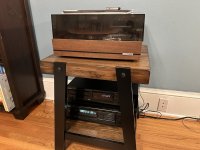
And he's the receiver in it's new home along with a vintage CD player I bought recently, and a vintage Dual turntable I found in a free pile. Portland free piles are hilarious, I have found 2 turntables, a receiver, and 2 guitars over the years along with lots of smaller stuff. Perfect for a cheap bastard like me. The "stereo stand" is also a recent $20 Goodwill purchase.
Thanks again!
I'm usually one of the people on the car forums trying to share my wisdom with the kids who want to learn how to fix and maintain their cars, it's fun to be on the learning end again.
And he's the receiver in it's new home along with a vintage CD player I bought recently, and a vintage Dual turntable I found in a free pile. Portland free piles are hilarious, I have found 2 turntables, a receiver, and 2 guitars over the years along with lots of smaller stuff. Perfect for a cheap bastard like me. The "stereo stand" is also a recent $20 Goodwill purchase.
Thanks again!
Attachments
I enjoy Wordle, but these challenges are even more fun, so thank you!
I owned a Dual 1019 several decades ago and gave it to my brother, but remember it fondly.
Best,
Steve
I owned a Dual 1019 several decades ago and gave it to my brother, but remember it fondly.
Best,
Steve
- Home
- Amplifiers
- Solid State
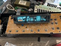
- Onkyo TX900 Display Not Working