I do see a fair red glow when it’s dark. Is that a sign of a working display? Pointing to a bad microprocessor or problem elsewhere?The filaments of the display are the end pins at each end of the display. Pins 1 and 2 are electrically the same as are pins 45 and 46. The filament voltage is measured between pin1/2 and pins 45/46
In the dark you might just make out the filaments glowing a very dull red and the display should feel slightly warm after a few minutes.
All the other pins should have a negative voltage on them, perhaps as much as -25 volts. If you get a resistor (say 4k7) and connect one end to ground and brush the other end over all the pins of the display (apart from the filaments) then different segments should illuminate really brightly. If that happens the display is OK.
If you suspect the uP is faulty then try removing the backup cap and leave it all for an hour or two with no power applied, then with the cap still removed apply power and see it the fault has changed.
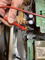
This transistor is the -26 volt regulator for the display. Check this voltage is OK.
View attachment 1234228
The backup cap.
View attachment 1234229
I found the transistor but it’s hard to get to. I need to go get some chores down outside while it’s dry then I will try to measure the voltage there.
Hugo, the memory cap voltage drops to 3.8V withe power off. Should I remove it and see if anything improves?
Hi,
I have the following suggestions for you to check. One micro pin 39. This is the reset of the micro and it should be high. if you ground it it will reset the micro. Two check pin 5. This is the Power off it should be zero volts. Third pin 26 micro clock but you need an scope to see if it is oscillating.
I have the following suggestions for you to check. One micro pin 39. This is the reset of the micro and it should be high. if you ground it it will reset the micro. Two check pin 5. This is the Power off it should be zero volts. Third pin 26 micro clock but you need an scope to see if it is oscillating.
Your original post. You indicate you get music through to the output. Are you able to adjust volume, select among the source inputs?!?!I picked up a vintage 1992ish Onkyo TX900 receiver from a neighbor recently. So far I have determined that the unit powers up, and has audio on both channels and through the headphone jack. But unfortunately the display isn't working.
If this is true, these are indications that the processor lives, at least partly, and the problem might be restricted to display trouble. If indeed this is the case, focus on the display circuitry. Look at the VF tube pins with your scope and you should find dynamic switching activity. This would be key evidence of a functioning processor and hope for a happy outcome. Perhaps a bias path has failed (see Mooly hints), or perhaps, sadly, the tube has lost its vacuum.
Thank you all again for the help, this has been awesome and a great learning experience.
One clarifying question so I don't damage anything. I'm assuming most voltages inside the unit are DC? Other than the main transformer? I have diagnosed more car audio which is all DC, so that's what I'm used to. And don't have a ton of experience.
But I checked for DC voltage on pin 39 on the micro and it was about 4.9V. But I also have 4.9V on pin 5. Is that telling the display micro to stay off?
Thanks, I will pull out the scope and give that a try.Your original post. You indicate you get music through to the output. Are you able to adjust volume, select among the source inputs?!?!
If this is true, these are indications that the processor lives, at least partly, and the problem might be restricted to display trouble. If indeed this is the case, focus on the display circuitry. Look at the VF tube pins with your scope and you should find dynamic switching activity. This would be key evidence of a functioning processor and hope for a happy outcome. Perhaps a bias path has failed (see Mooly hints), or perhaps, sadly, the tube has lost its vacuum.
Hi,
Micro pin5 is the power OFF signal. It should be zero when the amplifier is OFF
Micro pin5 is the power OFF signal. It should be zero when the amplifier is OFF
Last edited:
That shows the display is intact (vacuum) and probably good.I do see a fair red glow when it’s dark. Is that a sign of a working display? Pointing to a bad microprocessor or problem elsewhere?
uP's can fail but having said that they are always the very last suspect.Pointing to a bad microprocessor or problem elsewhere?
Just measure the voltage on the pins of the display. Any of them apart from the end pins. If it is on one it will be on them all. Do you have that -26 volts?I found the transistor but it’s hard to get to.
Good morning.
All very good points and most more 'to the point' than the ones I brought up.
The 3.8V on the cap is too low and the capacitance is 0.1 Farad, not 0.1µF.
At the moment that is the only component that for sure is not in good shape.
The -26V is on pin 56 of the µP if that helps.
Hugo
All very good points and most more 'to the point' than the ones I brought up.
The 3.8V on the cap is too low and the capacitance is 0.1 Farad, not 0.1µF.
At the moment that is the only component that for sure is not in good shape.
The -26V is on pin 56 of the µP if that helps.
Hugo

I did some research on these vacuum displays last night and came back to this suggestion this morning.The filaments of the display are the end pins at each end of the display. Pins 1 and 2 are electrically the same as are pins 45 and 46. The filament voltage is measured between pin1/2 and pins 45/46
In the dark you might just make out the filaments glowing a very dull red and the display should feel slightly warm after a few minutes.
All the other pins should have a negative voltage on them, perhaps as much as -25 volts. If you get a resistor (say 4k7) and connect one end to ground and brush the other end over all the pins of the display (apart from the filaments) then different segments should illuminate really brightly. If that happens the display is OK.
If you suspect the uP is faulty then try removing the backup cap and leave it all for an hour or two with no power applied, then with the cap still removed apply power and see it the fault has changed.
This transistor is the -26 volt regulator for the display. Check this voltage is OK.
View attachment 1234228
The backup cap.
View attachment 1234229
I only measured -2.78V on pin -B (on connector JL103. So I'm thinking that something in the voltage regulator circuit is bad. In one of the videos I saw a capacitor in that circuit had leaked and blown a resistor. When he jumped the resistor with a good one it came back to life.
I measured the resistance across R907 and get about 1.2 kOhm to start, then it slowly increases. Is this due to being in circuit with the other capacitors etc?
I need to pick up some resistors and I can try jumping that resistor and replacing it.
I measured all the voltages on connector JL103 just for good measure:
F - 5.0V AC across both F
F
-B -2.78V
E 0 V
5.5V 5.6V
PROT 0 V
P-OFF 4.73V
RELAY 4.83V
Thanks again,
Ian
Good sleuthing, Ian!
The voltages on the JL103 don't look correct to me. As I read the schematic, B- should be -26V (from emitter of Q203, can't read Q number with confidence) and the filaments should be biased at about -20V via D701, R701, R702--- but of course they won't read that because of incorrect -26V.
I've yet to see anything definitive for processor failure. The 0.1F cap is suspect, but that won't prevent operation. Processor seems to be enabling relay. Switching waveforms on tube pins would be an excellent sign.
I need to buy some resistors. Will 1/4 Watt resistors work? Or 1/2 Watr? or do I need something with a higher rating? R907 is pretty small.
The 10k could be faulty but it wouldn't be a first suspect as it is very lightly stressed 🙂 1/4 watt is fine for that one. You really need to isolate one end of the resistor to check it as in circuit checks on high value resistors is often inaccurate due to interactions with other parts.
Is the 10 ohm, R906 OK? That can be checked in circuit.
If it is open then replace the resistor and also these two caps. The way the caps are located on the diagram looks a bit odd to me but that doesn't matter, if that 10 ohm is duff then replace the caps.
Also if the 10 ohm has failed then its also possible the failure could be also be caused by the transistor becoming leaky and conducting into the Zener diode on the base of the transistor.
I measured R906 and it was right at 10 ohms.
What does the (1/2) signify after it? 1/2 watt? Or is that 1 of 2?
Given that I got a reading on R907 should I start by replacing the two caps in that circuit? And measure R907 once the caps are out?
What does the (1/2) signify after it? 1/2 watt? Or is that 1 of 2?
Given that I got a reading on R907 should I start by replacing the two caps in that circuit? And measure R907 once the caps are out?
I measured R906 and it was right at 10 ohms.
That's good then. The 1/2 is half watt.
Next up then is to do as BSST suggests and measure the voltage on the transistor. The 10 ohm being OK means you should have -40 volts or so on the collector (middle pin). It might be safer to measure the voltage on the Zener diode for the base volts as one slip with the meter probe would cause damage.
Not at this point... lets see where the voltage trail leads.Given that I got a reading on R907 should I start by replacing the two caps in that circuit?
It is good to find a fault by measurement rather than just changing parts but ultimately I'm probably going to say that unless the fault is 'just' the 10k having gone high (which it might well be) and which would be a genuine 'one off' fault then I would replace the caps and if the transistor or Zener proved faulty then I would do a blanket change of the caps and both the transistor and diode as well.
First lets try and find the fault and then analyse what might have happened to cause it.
Awesome guys thanks! Let me see if I can get in there and safely measure the voltages without pulling the board loose
- Home
- Amplifiers
- Solid State
- Onkyo TX900 Display Not Working