You've managed to capture base and emitter voltage that indicates a defective component somewhere in that region. It's probably inevitable that you'll have to gain access to the solder side for repair. Perhaps you just resign yourself to that task. But I would get a second opinion from Mooly. I'd also try to be pretty confident about processor viability before committing to dismantling.
Good point, I can go back and re-read how to check the processor before pulling it apart more.
Here's what I just measured:
I have -38.6V on one side or R907, and -1.7V on the other side
On Q903 it's currently reading:
B = -1.75V
E = -1.17V
C = -1.72V
At D909 I have -1.72V on one side, 0 on the other
Shouldn't I have -38.6 V on the base of the transistor if I'm reading the wiring diagram right?
Thanks,
Ian
You should have nearly -40V on collector, about -27V on the base (established by zener diode D909), and emitter voltage reduced about 0.6V re the base, i.e. about -26.4V. If there isn't ~-40V at the collector, that might be the sole problem, but there are many possible culprits.
Edit: I'll be more emphatic--- if there isn't almost -40V at the collector (sourced from that 10 Ohm), the circuit can't work. All the other voltages may be byproducts of the missing collector supply voltage.
Edit: I'll be more emphatic--- if there isn't almost -40V at the collector (sourced from that 10 Ohm), the circuit can't work. All the other voltages may be byproducts of the missing collector supply voltage.
Last edited:

OK ignore the above post. I got confused about which wires on the diagram were base, emitter and collector.
On the Base pin I measured -2.2 V
Emitter -1.6 V
Collector -38.8 V
R906 has -38.88 V on one side, -38.84 V on the other (10 ohm resistor doesn't drop voltage much eh?)
R903 has -12.34 V on one side, -38.8 V on the other
D909 has -2.2 V on one side, 0 V on the other
C916 has -38.8 V on one side, -2.2 V on the other
C917 has -2.2 V on one side, 0 on the other
C918 has -1.6V on one side, 0 on the other
Does this help? I'm off to research failing diodes and transistors.
Thanks!
Ian
Voltages across R907 would be useful--- should have collector and base voltages across its leads. If all were working properly, current through R907 would bias zener diode D909 to about -27V. Q903 would act as a "buffer" emitter follower and provide supply voltage about 0.6V lower re the base voltage, i.e. about -26.4V. The actual defect could be any of several possibilities: open R907, failed Q903, quasi shorts across D909 or C917.
I did measure voltage across R707, it was -38.8V and -2.2V. Forgot to add it to the post.
It sounds like I need to order a few parts!
It sounds like I need to order a few parts!
Just skimming through all the posts...
It just might be the 10k (not the 10 ohm, the 10k) gone high. You can dab another one across it as a test.
What values have you got... lots of values will work as a test.
But voltage at the Base is -1.79V and at the Emitter it’s -1.17V. It’s tight in there.
It just might be the 10k (not the 10 ohm, the 10k) gone high. You can dab another one across it as a test.
What values have you got... lots of values will work as a test.
R907 would have about 36V across. If it's detectably warm, it's probably not the problem. You could try an in-circuit resistance check, but be skeptical because of shunt paths. Test resistance with both meter polarities; any difference is likely to due to shunting semiconductor junctions. In unlikely case you see more than 10k in both directions, the 10k may be failed.
An open 10k would be lucky, as it might be patched without board removal. The most probable failure is the transistor, but there's no clear evidence either way.
An open 10k would be lucky, as it might be patched without board removal. The most probable failure is the transistor, but there's no clear evidence either way.
I tried measuring R707 today with the power off overnight. The resistance starts at about 1k and starts to climb.
Given that it's in parallel with a capacitor is it possible that the resistor is open and I'm actually measuring the capacitor resistance?
Once I get the resistors I will try jumping with a 10k and see if the display comes back on.
I tried looking for activity on pin 26 with my scope but just saw a voltage there. No waveforms, but I also might not have the scope set properly.
I'm not surprised by the ambiguous resistance readings--- hence my cautionary tests of polarity. Indeed, you're observing capacitor charging.
I'm also late in recognizing that without a working -26V supply, there won't be voltage present to reveal processor attempts to drive the display pins. Best to wait for likely resurrection of the -26 supply. Sorry for a futile suggestion.
I'm also late in recognizing that without a working -26V supply, there won't be voltage present to reveal processor attempts to drive the display pins. Best to wait for likely resurrection of the -26 supply. Sorry for a futile suggestion.
I apparently missed the little M on my scope. What I thought was 1k Ohm was actually 1 M ohm. Oops.Just skimming through all the posts...
It just might be the 10k (not the 10 ohm, the 10k) gone high. You can dab another one across it as a test.
What values have you got... lots of values will work as a test.
But in general wouldn't a higher resistance would cause a larger voltage drop?
It doesn't always work like that. The volt drop depends on the current (V=I*R). In your circuit the 10k has approx -40 at one end and because of the Zener diode a fixed -26 volt (whatever the Zener voltage is) at the other end.But in general wouldn't a higher resistance would cause a larger voltage drop?
That means 14 volts is dropped across the 10k resistor and the current is I=V/R which is 1.4 milliamps in the resistor. That current flows in the resistor and Zener.
That 1.4 milliamps is available as base current to the transistor and the current gain of the transistor (say 150) means that we can now draw a much higher current from the transistor emitter while retaining the stable -26 volts reference voltage at the base.
If the resistor went to 30k it might well still all work but the Zener current would start to be to low to develop the correct voltage across the Zener. The voltage across the Zener would fall a little and so the voltage across the now 30k resistor is higher. If you work the current out though it will be lower. For example 20 volts across the Zener means there is now 20 volts across the now 30k and the current is 0.66 milliamps.
OK my resistor set arrived.
Is there any harm in trying different resistor values across the existing R907 and see if the voltage at the emitter come up closer to 26V?
Or do I need to pull the board and pull that 10k resistor out and replace it?
And if I replace the 10k resistor and it still doesn't work is the Zener diode the next culprit? I guess at this point I could also remove it and test it.
I was going to try to do some math but I have to run out to an appointment and I'm more a "let's try this" vs. calculation kind of engineer. LOL.
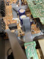
In the photo I'm pointing to the circuit we have been diagnosing. It doesn't look too hard to pull that main board up.

Thanks!
Ian
Is there any harm in trying different resistor values across the existing R907 and see if the voltage at the emitter come up closer to 26V?
Or do I need to pull the board and pull that 10k resistor out and replace it?
And if I replace the 10k resistor and it still doesn't work is the Zener diode the next culprit? I guess at this point I could also remove it and test it.
I was going to try to do some math but I have to run out to an appointment and I'm more a "let's try this" vs. calculation kind of engineer. LOL.
In the photo I'm pointing to the circuit we have been diagnosing. It doesn't look too hard to pull that main board up.
Thanks!
Ian
Just dab another 10k across the existing resistor. If nothing happens we look further.
If you pull the transistor out the voltage across the Zener should come up to -26 volts. That is the best way to test the Zener.
And if I replace the 10k resistor and it still doesn't work is the Zener diode the next culprit? I guess at this point I could also remove it and test it.
If you pull the transistor out the voltage across the Zener should come up to -26 volts. That is the best way to test the Zener.
Ok I inserted a 10k resistor across the pins for R907.
Before the voltages at the transistor were:
B -1.5V
E -0.93 V
C. -38.6 V
With the 10k resistor the voltages are:
B -2.9 V
E -2.3 V
C -38.6 V
Does this mean the resistor is doing something? If it was open this should make it work normally?
Before the voltages at the transistor were:
B -1.5V
E -0.93 V
C. -38.6 V
With the 10k resistor the voltages are:
B -2.9 V
E -2.3 V
C -38.6 V
Does this mean the resistor is doing something? If it was open this should make it work normally?
Attachments
I surmise you’ve paralleled a new 10k with the exiting R907. The original is probably ok, so you now have twice the current driving the base and Zener diode, so the voltage rises a bit.. The most likely explanation is that the transisto’s collector has opened. Remove the transistor and measure the base pad again. If you observe -27V, that’s confirmation of transistor failure.
Ok I removed Q903.
I now measure:
Across R907 and C916
-1.16 V
-39.1 V
Across C917 and D909
0 V
-1.16 V
Across C918
0 V
2.8V
Emitter 2.8V
I now measure:
Across R907 and C916
-1.16 V
-39.1 V
Across C917 and D909
0 V
-1.16 V
Across C918
0 V
2.8V
Emitter 2.8V
- Home
- Amplifiers
- Solid State
- Onkyo TX900 Display Not Working