Hi everybody.
my Onkyo A-8015 does not switch on the speakers anymore.
When I turn it on, there's power.😱 Normally after 5 seconds you hear a click when the speakers are switched on. This doen't happen anymore.😱
Anyone an idea why the relay doesn't switch anymore? I haven't the faintest idea if this is a common problem.😕😕
I guess it's a little glitch, because I have had this amplifier for at least 25 years without problems. I am much too pleased with this amplifier to toss it away.
Two common possibilities. Either excessive dc voltage on the speaker line so the amp has gone into protection mode to protect the spkrs. Or failure in the protect circuit, relay hasn't been activated after the mute time. Trypically a transistor, diode, cap or the relay. You will need to down load the service manual (hifiengine?) and take some basic voltage measurements. Do you have a meter/comfortable taking voltage measurements?
Apologies for the following description, the service manual does
not provide suitable diagrams.
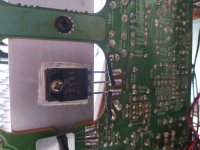
The output transistors will be mounted to the heatsink. Between
each pair of outputs will be two larger white (normally) emitter
resistors. In the immediate vicinity should be 3 pins Iid, E, VCT.
Measure dc voltage at pin Iid with black probe connected to chassis.
Expect less than 100mV. Repeat for other channel. Note sign +/- of
measured voltage.
Anything over about 400mV means you have a failure in that power
amp channel. If voltages are ok then next step is the protection circuit.
not provide suitable diagrams.
The output transistors will be mounted to the heatsink. Between
each pair of outputs will be two larger white (normally) emitter
resistors. In the immediate vicinity should be 3 pins Iid, E, VCT.
Measure dc voltage at pin Iid with black probe connected to chassis.
Expect less than 100mV. Repeat for other channel. Note sign +/- of
measured voltage.
Anything over about 400mV means you have a failure in that power
amp channel. If voltages are ok then next step is the protection circuit.
Last edited by a moderator:
hi everybody!
I have discovered that a diode, D505 in the schematic has been burned. an other one, D605 isn't in good shape also. This will probably cause the problem, for they are situated nearby the power amp section. the only issue is, that they are type VD1222. I have heard they can be repalced by two type 1N4148 who you have to solder in series, according to this atricle:
VD-1221 Replacement Substitute Diodes | RETROVOLTAGE


hi everybody!
I have discovered that a diode, D505 in the schematic has been burned. an other one, D605 isn't in good shape also. This will probably cause the problem, for they are situated nearby the power amp section. the only issue is, that they are type VD1222. I have heard they can be repalced by two type 1N4148 who you have to solder in series, according to this atricle:
VD-1221 Replacement Substitute Diodes | RETROVOLTAGE
That seems reasonable, they are rated as between 1.24 and 1.34 forwards voltage at 1.5mA with -3.6mV/C tempco. They are to stabilize the bias as they are thermally coupled to the output devices.
You will need to re-adjust the bias after installing the replacements.
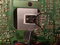
Just replaced the diodes with 2xN4148, but......no effect. The speakers are still not switched on. Anyone suggestions what to do now??
Just replaced the diodes with 2xN4148, but......no effect. The speakers are still not switched on. Anyone suggestions what to do now??
Show a photo of how you have soldered in the 2 x 1n4148s?
If you press power button and absolutely nothing happens(no lights, dead quietness) this means problem is in power switch
Check power switch with multimeter. See if it works.
Also if you have additional power outlets in the rear of the receiver make sure all those are well connected.
Check power switch with multimeter. See if it works.
Also if you have additional power outlets in the rear of the receiver make sure all those are well connected.


If you press power button and absolutely nothing happens(no lights, dead quietness) this means problem is in power switch
Check power switch with multimeter. See if it works.
Also if you have additional power outlets in the rear of the receiver make sure all those are well connected.
When I press the power switch, the amplifier switches on. All lights and stuff working. only the speaker relay does not switch on, you don't hear the click that switches on your speakers....
That sounds like the amplifier may have a fault such as high DC offset on one of the channels and the protection circuit is therefore deliberately not connecting the speakers in order to protect them.
Just measure the DC voltage on the speaker feed to the 'input' side of the relay contacts. It should be near zero for both channels.
Just measure the DC voltage on the speaker feed to the 'input' side of the relay contacts. It should be near zero for both channels.
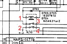
I'm not sure between what points exactly I have to measure.
Can you tell me between which points where exactly to measure?
Between point 1 and ground and point 2 and ground also?
See picture of service manual..
Can you tell me between which points where exactly to measure?
Between point 1 and ground and point 2 and ground also?
See picture of service manual..
Attachments
Last edited:
I'm not sure between what points exactly I have to measure.
Can you tell me between which points where exactly to measure?
Between point 1 and ground and point 2 and ground also?
See picture of service manual..
All four points should have zero volts DC but assuming that the input side is at the left then that simplifies to points 1 and 2.
between point 1 and ground (left channel) measured 0V
between point 2 and ground (right channel) measured 10V negative!
So the problem should be in the right channel.....but where???
between point 2 and ground (right channel) measured 10V negative!
So the problem should be in the right channel.....but where???
Last edited:
Probably not the outputs by the looks of it. The feedback loop appears to be broken somewhere. Open feedback resistor, bad input FET or cascode transistor, bad VAS transistor would be typical causes.
Time to whip out the multimeter in diode test and ohmmeter mode (power off). Check R615 (68k). Starting on the input side, make sure every transistor has its two p-n junctions and every diode checks out fine. Make sure the input FET is not obviously shorted.
Watch out for suspect-looking solder joints while you're at it. Also, do you see any burned resistors or somesuch? Something like this could accelerate the search considerably, it can get a bit tedious otherwise (it's a moderately complex amplifier).
The good news is that you've got a good channel to compare to in case you are not sure whether your readings are normal.
between point 1 and ground (left channel) measured 0V
between point 2 and ground (right channel) measured 10V negative!
So the problem should be in the right channel.....but where???
Experience says probably an output problem... you will have to get measuring. If any low value 'emitter resistors' have failed open circuit then its possible the driver stages (which may also have failed in response) might be creating this negative 10 volts. Other possibilities could be a local supply within that channel that is missing, something like a Zener derived bias voltage.
First two checks with the amp OFF are to check continuity between C and E of the output transistors in that channel and also to measure the emitter resistors.
Next step is to come up with a clear circuit diagram so that we can advise better.
It sounds like this may be outside your comfort zone tbh 🙂 although you can still do the basic checks.
- Home
- Amplifiers
- Solid State
- onkyo A-8015 does not turn on