I would check the Variable resistor R538 10k ohms while you are at it. Next to (D505 D1222), They get old, oxidized and flaky. I always replace them as a matter of course with 25 turn sealed VRs like the Bourns type.
Attachments
Last edited:
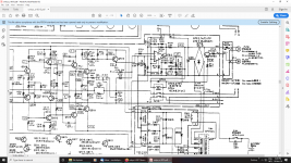
In order to meet Moody's request, I've attached the service manual.....
Still think it's strange the manual has no PCB layouts and no measuring points in the schematic to check where things can go wrong...
the varistors(there are only two varistors on the entire PCB!)seem not to be that bad, but I'll check them to see if the misvoltage changes when I change their position. It's something I only have to check with the right channel.
Attachments
Things can go wrong anywhere... and tbh a service tech would need only a few basic measurements to get an idea of where the problem lies and would be able to work at that level without a diagram.... however 🙂
You need to check the all the supplies on the faulty channel. Checking supplies is always the first rule in faultfinding. So that means the - and + 42 volts applied to the output stage and drivers.
Next check the auxilliary - and + 20 volt rails. A convenient point to check these is on the supply pins of the opamp which is used as a DC servo. There should be -/+20 volts on pins 4 and 8.
Now with the amp off check the value of the 0.47 ohm resistors connected to the emitter of the output transistors. Remember these are low in value and so you must subtract your meter lead resistance (the reading you get with probes shorted) to the measured value. In practice if you would probably see something like 0.68 ohm or lower.
Now check both output transistors for reading low ohms or short circuit between C and E. They should not read low/short.
Check both 2.7 ohm resistors that feed the base's.
Lets see what all that shows.
If we still haven't a diagnosis then the next step is detailed voltage checks on the circuit measuring at key points.
Have a look at the schematic, there are test points with voltages. This should show you in two minutes in which stage the fault is located. Be sure to have the amp set as the manual describes at the end of page 4! Otherwise the voltages may not be correct. Measure the voltages at the test points and report. Onkyo has easy to follow layouts.
It's not that easy with voltages in complex DC-coupled amplifiers with global feedback. Relative voltage readings can be quite useful, e.g. when a B-E drop is either >>0.6 V (open) or <<0.6 V (shorted). Absolute readings, often not so much, except maybe at the very input - compare the voltage at both FET gates, there should be a near-zero differential.
Checking the resistors in the output stage tends to be a good idea just in case.
Checking the resistors in the output stage tends to be a good idea just in case.
Turbowatch2, thanks! I've found the voltages in the schematic and the testpoints also.
seems I completely overlooked it. Now I can go ahead and measure some. I assume LOAD open means with no speakers connected.
seems I completely overlooked it. Now I can go ahead and measure some. I assume LOAD open means with no speakers connected.
I have made it more clearly in the schematic. Think I'll print it out tomorrow.
I still find it hard to believe that an appliance like this, which functionated well for over 30 years, behaves like this...
I still find it hard to believe that an appliance like this, which functionated well for over 30 years, behaves like this...
Attachments

Last edited:
Something I missed earlier and that is that there is a third 0.47 ohm feeding the supply to the collector of the upper NPN output transistor.
Be sure to check that there is +42 volts on each end of this resistor.
Be sure to check that there is +42 volts on each end of this resistor.
Turbowatch2, I've measured both points, for L and R channel as explained on page 4 of the manual.
R channel could be set to 12V, but L channel is and stays 0V, whatever I do with the varistor.
R channel could be set to 12V, but L channel is and stays 0V, whatever I do with the varistor.
The left channel stays at 'zero' volts because the normal voltage and adjustment range is so tiny... it is MILLIVOLTS, not volts.
If you have disturbed the good channel setting then you MUST reset that correctly or risk having that channel fail as well.
Being able to set the right channel to '12 volts' has confirmed that the 0.47 ohm resistors are open circuit assuming you really have got 12 volts across those test points.
Page 4 of the manual says to set the value to 12 millivolts -/+5 mv.
So reset the good channel before doing anything more.
Does that mean that both channels should be 12mV?? There are three pins on the PCB for both channels. Vct, Iid and E.
12V was measured between Vct and E on the R channel, not between Vct and Iid.
Is the main issue to get a value of 12mV between Vct and Iid or both channels in order for the amplifier to switch on the power amp?
Sorry, but for doing measerements in amplifiers, I'm a complete newbie......
12V was measured between Vct and E on the R channel, not between Vct and Iid.
Is the main issue to get a value of 12mV between Vct and Iid or both channels in order for the amplifier to switch on the power amp?
Sorry, but for doing measerements in amplifiers, I'm a complete newbie......
Last edited:
The method given in the manual is a bit strange because it probably assumes point VCT is at zero volts...
All the preset does is alter the bias current which is the static current flow in the output transistors. 12mv across 0.47 is around 25 milliamps (ohms law) and that would be in the right ballpark. Measuring voltage across these resistors is the standard way of setting bias current in 99% of amplifiers.
This bias current has absolutely no impact on the DC offset you are measuring, all it does is minimise distortion.
If you set the value to high then the stage will run to hot and could enter a situation called thermal runaway. So reset the good channel back to approx the 12 millivolts required.
- Home
- Amplifiers
- Solid State
- onkyo A-8015 does not turn on