Professional finish by a "newbie". Great work, Scott! I also finished mine recently, a significant improvement over the Zen Balanced line stage. Thank you Mr. Pass and Veteran.
WC
WC
Pars:
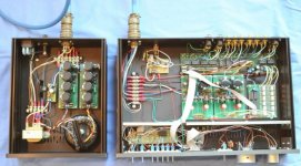
The enclosures came from HiFi2000 and I am very pleased with the quality. I purchased the 10mm front panels for both the preamplifier and the power supply enclosures and love them -- HiFi2000's products are a bargain at the price (even with shipping to the US). I spent months tweaking the front and rear panel designs and then had Front Panel Express do the drilling and engraving. FPE isn't inexpensive, but they also do beautiful work.
The power supply photos weren't particularly good, but here is one shot.
Teake:
I am very excited by the Aleph P -- it will replace a beloved Rowland Coherence 1 mk II preamplifier which has performed flawlessly in my main system for many years. The Rowland is grainless, smooth and very clean sounding, with great resolution and a nice broad soundstage. It also has an exceptional phono stage. Initial listening impressions with the Aleph P (after extensive break-in) are that it has a closer, slightly more intimate presentation, is very smooth and has no discernable grain, also has a clearly defined and broad soundstage and is slightly warmer in tone (not surprisingly, a good match for my Aleph amps). My last project was the Pearl / Ono phono preamp (Promitheus' group buy), which also turned out very well and is already in use with the Aleph P.
Before starting on this project, I thought it was hubris to try to better a preamp as exquisite as the Coherence 1 mk II. Now, I'm not so sure.
Everyone:
Many of you guys know what you're doing. Some of us, myself included, don't. Without this forum, I never would have delved into DIY audio. So on a heartfelt level, thank you again for all of your support and the very instructive posts.
Regards,
Scott
Attachments
SRMcgee, Where did you get the lcd display and how hard are they to program. Can you choose whatever you want to display on the screen in reference to an input/output or volume. Really nice job.
I like the external power connection, but not on the same wavelength as Jacco. Tad
I like the external power connection, but not on the same wavelength as Jacco. Tad
Tad:
I wanted a blue/white LCD display and found something suitable and inexpensive (http://www.quickbearings.com/sc/store.php?crn=212&rn=385&action=show_detail). The remote control system (balanced input selector, balanced attenuator, front panel control board and CPU board) were all sourced from Mikkel Simonsen (http://electronics.dantimax.dk/), whose products and service are highly recommended. Mikkel's Dantimax systems allow for programming labels for the various inputs, so the credit goes to him. The actual programming is very easy, but on a 2x16 character display you only really get 1x13 characters to label (the top line of the display is reserved for the volume of the two channels plus space for "Mute" to appear, and the last three characters on the bottom line are reserved for " TM", which appears when the tape monitor is engaged).
Regards,
Scott
It seems that they will be no new GB for Aleph P Boards - does anybody have the PCB Gerber/Eagle files?
regards
Aykman
regards
Aykman
Who wants to sell his PCB boards?
Do anybody want to sell his unused veteran aleph p pcb boards?
I need one set of PCB (incl. PSU pcb). Pleae no offers for complete soldered Aleph P PreAmps - just the PCBs. Thanks
Contact via PM or email.
Payment via PayPal
regards
Alan
Do anybody want to sell his unused veteran aleph p pcb boards?
I need one set of PCB (incl. PSU pcb). Pleae no offers for complete soldered Aleph P PreAmps - just the PCBs. Thanks
Contact via PM or email.
Payment via PayPal
regards
Alan
Power Supply Issue
Folks:
I'd appreciate some expert advice. My new Aleph P 1.7 is working beautifully but a friend of mine, who is even more of a newbie than me, is having a problem. He and I decided to build two AP17s together and he has had problems with one of his power supplies. I offered to try to debug the issue but am stumped. Here are the results of my initial readings:
Good -------- Bad
PS ----------- PS
94.8 vdc --- 94.9 vdc ---- Reading across 1st big cap
94.7 vdc --- 95.1 vdc ---- Reading across 2nd big cap
64 vdc ----- 93.8 vdc ---- Reading across 3rd big cap
63.9 vdc --- 95 vdc ------ Reading across 4th big cap
63.9 vdc --- 95 vdc ------ Voltage at output
I'm feeling guilty because he trusted me to help him complete his project and I'm lost. The only diagnostic tool I have is a multimeter. Can anyone help me debug the problem with my friend's second power supply?
Much appreciated,
Scott
spzzzzkt:
Is there a way to test a zener diode (and if so, how), or must I replace the entire string?
Thanks,
Scott
p.s.: It probably goes without saying, given this thread, but the PCBs are Veteran's AP17 boards.
Is there a way to test a zener diode (and if so, how), or must I replace the entire string?
Thanks,
Scott
p.s.: It probably goes without saying, given this thread, but the PCBs are Veteran's AP17 boards.
Check that orientation is correct, and check that you are getting the correct voltage drop across each zener.
From the schematic it looks like you should be seeing 63.7V drop across the entire zener string.
From the schematic it looks like you should be seeing 63.7V drop across the entire zener string.
Should check voltage drop across R1 of the schematic too.
Sounds like the mosfet is dead too for the 4th cap to have the same voltage as the rest.
Zen ver 3 from pass diy has a nice writeup about the regulator in the powersupply
Sounds like the mosfet is dead too for the 4th cap to have the same voltage as the rest.
Zen ver 3 from pass diy has a nice writeup about the regulator in the powersupply
zenesh and spzzzzkt:
Thanks for the advice so far. I checked the voltages across the zener diodes on both the good and bad boards and saw little difference. I'll check R1 next and then try replacing the mosfet.
Regards,
Scott
Thanks for the advice so far. I checked the voltages across the zener diodes on both the good and bad boards and saw little difference. I'll check R1 next and then try replacing the mosfet.
Regards,
Scott
Hi Guy,
it's ok if i got -0.4 V in - output and 0.2 V in + output ?
Volatge across output caps is 30 V
it's ok if i got -0.4 V in - output and 0.2 V in + output ?
Volatge across output caps is 30 V
Folks:
This is getting increasingly embarrassing. I had one AP17 power supply that was working fine and another that clearly had a problem (Veteran's PCBs; see posts above). In trying to diagnose the issue, I screwed things up further by damaging the good power supply. I have now replaced the IRF610 transistors on both PCBs but am getting identical readings from both supplies, which are each generating between 83 and 85 VDC.
Is there a way to determine whether a zener diode has been damaged? I'm unsure of how to determine which, if any, of the 9.1V diodes have been blown on each PCB. Is it likely that something else has been blown instead?
This is a learning process, certainly, but I wish my ignorance didn't have to be so publicly displayed. Any advice you can offer will be appreciated.
Regards,
Scott
I'll go ahead and display my ignorance, as I don't know what the typical failure mode for a zener diode is. If you take a DMM and measure the voltage drop from the cathode (+ lead) to the anode (- lead) of each diode, you should see ~9.1Vdc. It would appear that your diode string is not conducting (reverse breakdown) with an output voltage of ~83-85Vdc? With 7 diodes, that string should drop a max of ~64Vdc.
Hi Scott
If your voltage at the output is too high, my guess is that one of the diodes is not conducting.
I would first measure the voltage drop over the resistor feeding the zeners to see if any current is flowing through them.
To make sure that a broken fet can influence this, I would suggest to remove the fets and first make sure the voltage at the gate connection is around 64V as Pars suggested.
When this is OK, then connect the fets. The voltage then should be ~60V at the drain.
Success...
Aaarrrgghh!
Folks:
This newbie has gotten one of the two AP17 power supplies on the non-working preamp running properly again, but for the life of me, I cannot figure out the problem with the other. The diode string is working fine -- about 9.1 volts is dropping across each. But the power supply output is still in the 90+ VDC range.
With the IRF610 removed, I'm getting 2.6 V at the gate, 98 V at the drain and 0 V at the source.
With the IRF610 installed, I'm getting 88.5 V at the gate, 97.4 V at the drain and 92.9 V at the source. The power supply's output is also 92.9 V.
Any counsel you can offer would be appreciated. I've been staring at the power supply so long I've grown blind.
Thank you,
Scott
Hi Scott,
If the zeners are working correctly, you should be getting around 64V at the gate when the fet is removed.
What is the current that is running through the zeners?
As long as the gate voltage is not around 64 V you will not ever get an output voltage close to 60V.
Success!
If the zeners are working correctly, you should be getting around 64V at the gate when the fet is removed.
What is the current that is running through the zeners?
As long as the gate voltage is not around 64 V you will not ever get an output voltage close to 60V.
Success!
- Status
- Not open for further replies.
- Home
- Group Buys
- (one more) ALEPH P 1.7 clone