Harris/Fairchild are the recommended brands.
Landoctor is selling matched sets over in the Trading Post.
http://www.diyaudio.com/forums/showthread.php?postid=1401685#post1401685
IRF is fine for the 610's.
heres a few posts by NP on the subject:
http://www.diyaudio.com/forums/showthread.php?s=&postid=1273543&highlight=9610#post1273543
http://www.diyaudio.com/forums/showthread.php?postid=1248500#post1248500
http://www.diyaudio.com/forums/showthread.php?s=&postid=1219682&highlight=#post1219682
ps i posted recently asking for sources for the harris irf9610 in the pass labs forum. the responses have current fairchild part numbers for substitutes for irf9610.
power supply problems
Hi all,
Powered it up and measured a good 60 volts DC from the power supply.
After hooking it to the preamp, i think i blew the power supply mosfet and it was only giving 5 volts DC.
Disconnected the preamp board and poked further at the PSU.
Few voltages here.
The string of zeners report a voltage of 63.2V
Drain of mosfet to ground gives 86V
Gate of mosfet to ground gives 86V
Source gives 5V
I think i have busted the mosfet and also have a bad protection diode D5 in Veterans schematic. Am I correct with the analysis?
Dumb P1 Question
Folks:
Please forgive the dumb newbie question, but how do you tell if P1 is adjusted properly? What should I be measuring?
Thank you,
Scott
Folks:
Please forgive the dumb newbie question, but how do you tell if P1 is adjusted properly? What should I be measuring?
Thank you,
Scott
I think it sets the gain of the circuit. The higher the value the lower the gain, the lower the distortion.
THis is with reference to Bride of zen preamp.
Regards
THis is with reference to Bride of zen preamp.
Regards
I discovered I'd posted the following to another P1.7 thread a while back - glad I can search to remind myself 🙂
Pretty much confirms what zenesh says....
---
The 2K trimpots are used to set the gain of the stage. On the original p1.7 these were panel mounted pots and were designated left and right gain.
The Aleph P user manual describes their function:
Pretty much confirms what zenesh says....
---
The 2K trimpots are used to set the gain of the stage. On the original p1.7 these were panel mounted pots and were designated left and right gain.
The Aleph P user manual describes their function:
Adjustment to optimize the level controls against an input level is easy. Select the most important input. Set the Right and Left level controls at minimum gain (counterclockwise)
and adjust the Master level control to as high as you will want to listen. If you don’t have
enough gain, then increase the levels on the Left and Right level controls until you do.
For maximum performance, the idea is to keep the Master control as clockwise as possible,
and the Left and Right level controls as counterclockwise as possible.
Folks:
Sorry for the dumb question, but I've been trying to figure out whether the heatsinks on T1, T2 and T3, and T8, T9 and T10, must be isolated from each other, or whether the fins can touch. I have isolated the heatsinks from the transistors themselves using mica pads, but cannot figure out how to keep fins from one heatsink from touching the fins on another.
Much appreciated!
Regards,
Scott
SRMcGee said:
Sorry for the dumb question,
If you have isolated the Mosfets it's pretty much irrelevant if the fins touch or not. Not that heatsinks are actually needed.
Probably I am one of the last to work on this pcb...
For now the caps in the signal path are Panasonic FC.
If all is going I will order BG N type.
I am wandering if someone want to look the measure I did.
Suggestion for further measurements are welcome.
Thanks in advance 🙂
Peppe
For now the caps in the signal path are Panasonic FC.
If all is going I will order BG N type.
I am wandering if someone want to look the measure I did.
Suggestion for further measurements are welcome.
Thanks in advance 🙂
Peppe
Attachments
Peppe,
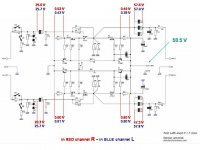
I'm pretty sure the voltages across input and output caps look double what they should be. You should have 12-15V over the input caps and roughly double that (ie around 30V) on the output caps. I've got 50V BG's on the outputs and they would be toast with the voltages you list.
I'd be checking all components for correct orientation for a start. If you have used the ZTX transistors make sure they are right way round as the shape is a bit ambiguous.
cheers
Paul
Hi Paul,
I will check the ZTX transistors orientation asap.
Actually I am not at home for working reasons.
I remeber the ambiguous shape of transistors and I am quite
sure I used attention before soldering them. (picture helps?)
Did I was wrong 4 time on 4 chance?!
I appreciate your suggestion, hope to update information asap.
Thanks 🙂
Peppe
Attachments
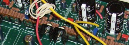

From the pics the ZTX appear to be correct, so cross that off the "to check list" 😉
Check your input gain switch settings too... There are three switch combinations that work, and I had a few problems when they were in fourth "illegal" setup.
http://www.diyaudio.com/forums/showthread.php?postid=1097060#post1097060
I don't think this is enough to cause doubled voltages but worth checking anyway.
cheers
Paul
Hi Peppe
how did you measure the voltages? did you ground the input before measuring?
cheers,
c.
how did you measure the voltages? did you ground the input before measuring?
cheers,
c.
Peppe,
C2 on both boards looks like it's around the wrong way. Positive should be oriented to inputs. The inputs are Positive (+) and Inverted (-) Signals, not +/- voltages.
edit: check the orientation of the output caps too... Same thing: cap positive towards the inputs for all caps. it looks like you have (-) Inverted output caps reversed.
cheers
Paul
spzzzzkt said:From the pics the ZTX appear to be correct, so cross that off the "to check list" 😉
Yes Paul, and I remember I checked all transistors (with the tester) before soldering them and I chose the ZTX with closer values as well.
Check your input gain switch settings too... There are three switch combinations that work, and I had a few problems when they were in fourth "illegal" setup.
I tested the output with an old headphone and there was audible music in each rail. I switched different combination as veteran indication (I got the scheme at home) and the music was more or less loud as expected by the scheme.
culture said:
how did you measure the voltages? did you ground the input before measuring?
No, I did not ground the input.
spzzzzkt said:Peppe,
edit: check the orientation of the output caps too... Same thing: cap positive towards the inputs for all caps. it looks like you have (-) Inverted output caps reversed.
Ok, here there was my big doubt. So I did different test:
input cap + oriented to (+) input and
input cap - oriented to (-) input
output cap + oriented to (+) output and
output cap - oriented to (-) output
than
input cap + oriented to (+) input and
input cap + oriented to (-) input
output cap + oriented to (+) output and
output cap + oriented to (-) output
and last configuration
(not in picture but that one I reported the measurements)
input cap - oriented to (+) input and
input cap - oriented to (-) input
output cap - oriented to (+) output and
output cap - oriented to (-) output
In ALL those configurations the measurements were the same (plus o minus 0.5 Volt) .
Arg... I am in trouble....
cheers
Peppe
So next check will be:
input cap +oriented to (+) input and
input cap + oriented to (-) input
output cap - oriented to (+) output and
output cap - oriented to (-) output
Is that right, Paul?
cheers
Peppe
input cap +oriented to (+) input and
input cap + oriented to (-) input
output cap - oriented to (+) output and
output cap - oriented to (-) output
Is that right, Paul?
cheers
Peppe
sorry for disturbing your dicussion,
but to someone who is comfortabe in veteran boards: what is the difference in gain settings between the pot in the middle of the board (is there a "ideal" meaurable setting) and the dips??
thx
stefan
but to someone who is comfortabe in veteran boards: what is the difference in gain settings between the pot in the middle of the board (is there a "ideal" meaurable setting) and the dips??
thx
stefan
Peppe said:So next check will be:
input cap +oriented to (+) input and
input cap + oriented to (-) input
output cap - oriented to (+) output and
output cap - oriented to (-) output
Is that right, Paul?
cheers
Peppe
That is definitely how I would have the caps installed. cap + should be oriented to signal source.
noelectrix said:sorry for disturbing your dicussion,
but to someone who is comfortabe in veteran boards: what is the difference in gain settings between the pot in the middle of the board (is there a "ideal" meaurable setting) and the dips??
thx
stefan
The pot in the middle of the board was panel mounted in the Pass Aleph P and is referred to as Left/Right Level control in the user manual.
Aleph P Manual says :
Adjustment to optimize the level controls against an input level is easy. Select the most important input. Set the Right and Left level controls at minimum gain (counterclockwise) and adjust the Master level control to as high as you will want to listen. If you don’t have
enough gain, then increase the levels on the Left and Right level controls until you do.
For maximum performance, the idea is to keep the Master control as clockwise as possible,
and the Left and Right level controls as counterclockwise as possible
We have set the maximum input so that the circuit will remain linear with balanced input peaks up to about 18 volts. If you are concerned that your source will approach or exceed this level, you may use the internal attenuator switch to reduce the input by 12 dB.
The switch default position is 1,2,7,8 = ON and 3,4,5,6 = OFF. For a 12 dB input
attenuation, 1,2,7,8 = OFF and 3,4,5,6 = ON.
This switch can also be used to effectively lower the gain of the preamp by 12 dB. It does
not otherwise affect the performance of the preamp.
hope this helps
Paul
- Status
- Not open for further replies.
- Home
- Group Buys
- (one more) ALEPH P 1.7 clone