I have received both the F3 boards from canada and the Aleph P boards about 1 week since i made payment. Advantages of living in a small country. Hang on tight. the packages are on the Way!
Single buck for a lines filter!? Was looking for an IEC with the switch and filter they cost like S$50 each.
Must search more =)
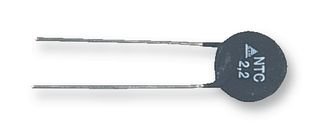
Was looking out for thermistors and found this rated at 5ohm max current of 5A. This would be fine yeah? Its a bit pricey being S$2 each
How many would we need? Say 1 for channel and 1 for power supply bring total to 4+1?
Farnell(sg) catalog number
9754172
Single buck for a lines filter!? Was looking for an IEC with the switch and filter they cost like S$50 each.
Must search more =)
Was looking out for thermistors and found this rated at 5ohm max current of 5A. This would be fine yeah? Its a bit pricey being S$2 each
How many would we need? Say 1 for channel and 1 for power supply bring total to 4+1?
Farnell(sg) catalog number
9754172
Attachments
Jacco
That would probably just be big enough for Nelson's 16000 watt pure class A amp --- but only in mono. Tad
That would probably just be big enough for Nelson's 16000 watt pure class A amp --- but only in mono. Tad
You're welcome to send NP a request to sign you up as member of the Pass Monster amp crew, maybe we'll see it orbit after all.
Something for transformer calculators.
Punch in the desired secondary voltages and output currents, and you'll get the EI core size and primary data.
(in German, but easy to comprehend, otherwise ask)
=>
Something for transformer calculators.
Punch in the desired secondary voltages and output currents, and you'll get the EI core size and primary data.
(in German, but easy to comprehend, otherwise ask)
=>
Attachments
I have received both the F3 boards from canada and the Aleph P boards about 1 week since i made payment. Advantages of living in a small country. Hang on tight. the packages are on the Way!
It is not a problem of small vs. big country. It is only a problem of good vs. bad quality of service.
Italian Post is baaaaaaaaaad!!!
Hi Wineds,
Nothing here either...
We might have to design our own boards.... I’m already trying to figure out how to do that 🙂
I build my pearl; F4 is starting to take shape... still need something in the middle... all the parts are there, only the pcb is still missing 🙁
But there is still a lot of other work to be done (chassis) so I’m not really in a hurry though I would like to know what I can expect..
Cheers,
C.
With regards to placing a attenuator at the output? What values are best? From reading in this thread and others, 1k, 2k, 5k and 10k are suggested.
As always, I am interested to know the why and even the maths
Thanks
As always, I am interested to know the why and even the maths
Thanks
Don't know why or the math, but as far as i know it should be 1k when on the output. Anyways, thats what Mikkel from Dantimax told me (and sold me), i use his relvol board.
Cheers,
C.
Cheers,
C.
zenesh said:the why
The output of the P1.7 is a current source=> high output impedance
Because of the current source, we should put a low value attenuator at the output in order to not increase the impedance seen by the amp? or increase the load on the mosfets?
What is the effect if high value attenuator is used? Loss of dynamics? Thanks for your answers Culture and Jacco.
I got a 10k step attenuator kit from DIYzone. I would need to get a whole new set of resistors if I am changing it to 1k attenuator.
What is the effect if high value attenuator is used? Loss of dynamics? Thanks for your answers Culture and Jacco.
I got a 10k step attenuator kit from DIYzone. I would need to get a whole new set of resistors if I am changing it to 1k attenuator.
It's good to know that Polish post office delivers all the foreign packages better than local one 
Hi,
I did a first test today and one channel seems to be fine but the other channel is not functioning right now. I dont measure anything across r25/r29 it should be 29volts. Also nothing across r27/r28. t3/t10 dont heat up either. I think it's a bit weird both + and - channel don't work.
anybody suggestions?
Oke, after swapping fets and transistors i found out i used 22k resisors instead of 22r resistors for r35/r36. measured values look oke right now and the fest heat up nicely... think i'll attach them to a piece of copper or some of those chipset heatsinks
so what have we learned today:
1) dont just double check.. at least triple check at least
2) pointing resistor values upwards was a great idea
3) put questions in the right place.... not in group buy
cheers
c.
so what have we learned today:
1) dont just double check.. at least triple check at least
2) pointing resistor values upwards was a great idea
3) put questions in the right place.... not in group buy
cheers
c.
veteran said:Nice to know that most of you received AP boards without any problems 😉
If you are looking for a volume controller for this project, now, when I have WM8816 chips I can prepare few more sets of my WMSTAMP. It can support XLR/RCA configuration with -111.5dB to +10.0dB control range in 0.5dB/2.5dB steps. On driver PCB you will find connector for source selector.
An externally hosted image should be here but it was not working when we last tested it.
Hiii Veteran
Do you finish making this volume controller ?
Regards, jeffry
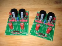
Finally my p1.7 is coming alive. Unfortunately one channel so far becouse i'm still waiting for the diodes for the second psu board.
Today I only made one really stupid mistake by connecting the psu board the wrong way around... stupid stupid stupid!!! (i had a bit to much to drink yesterday...) one smoking resistor and a broken fet.... lucky me i didn't connect the amp board.
Think adding a piece of coper (or whatever) to the fets isn't bad idea because they get really hot
Anyway this is what the pile of pcbs looks like so far
cheers
c.
Attachments
Looks good man! Mojo, Teake
And don't drink whan you'' re soldering or getting your stuff together. I learnt from that, it can destroy a lot, good listening
And don't drink whan you'' re soldering or getting your stuff together. I learnt from that, it can destroy a lot, good listening
Dear Veteran
I try to contact you by email before
I already order and pay you by paypal for
WMStamp several month ago but i didnt receive
it and didnt have any information too
I just want to asking you
- do you finished your WMStamp PCB ?
- do you send me your PCB set ? ( more than US$ 100 )
- If not, when you can send me the PCB ?
Sorry for disturbing, but i need it to make my preamp work
Regards, Jeffry
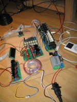
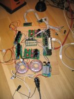
And we have stereo!!! and no smoke this time 🙂
I only need build a chassis now.. wonder if my metal working skills are on par.... Anyway, the amps sound nice so far, no hum, no weird distortion or whatever. it only needs a decent power amp 🙂 but f4 power is on it's way 🙂
cheers,
c.
I only need build a chassis now.. wonder if my metal working skills are on par.... Anyway, the amps sound nice so far, no hum, no weird distortion or whatever. it only needs a decent power amp 🙂 but f4 power is on it's way 🙂
cheers,
c.
Attachments
- Status
- Not open for further replies.
- Home
- Group Buys
- (one more) ALEPH P 1.7 clone