Doesn't matter how many 4P1l's you parallel, the tube is limited in its voltage swing capability. To gain power you have to move to a lower ratio OPT. Seems the 6C4C the better choice than paralell pair of 4p1l for more power output low cost DHT? Asking cause I am sitting on 2 pairs of 4P1ls, need 5-6Vrms output into 38 ohms planar headphone drivers.
Doesn't matter how many 4P1l's you parallel, the tube is limited in its voltage swing capability. To gain power you have to move to a lower ratio OPT. Seems the 6C4C the better choice than paralell pair of 4p1l for more power output low cost DHT? Asking cause I am sitting on 2 pairs of 4P1ls, need 5-6Vrms output into 38 ohms planar headphone drivers.
The lower is ratio of OPT, the easier to make it of higher quality. That's the main point.
It is interesting to have experimented with 12P17L, very interesting?
No, I did not. But I am pretty sure results will be very good.
I want to try, but never seem to find this lamp (12P17L) the internal resistance, which would calculate the output transformer
I want to try, but never seem to find this lamp (12P17L) the internal resistance, which would calculate the output transformer
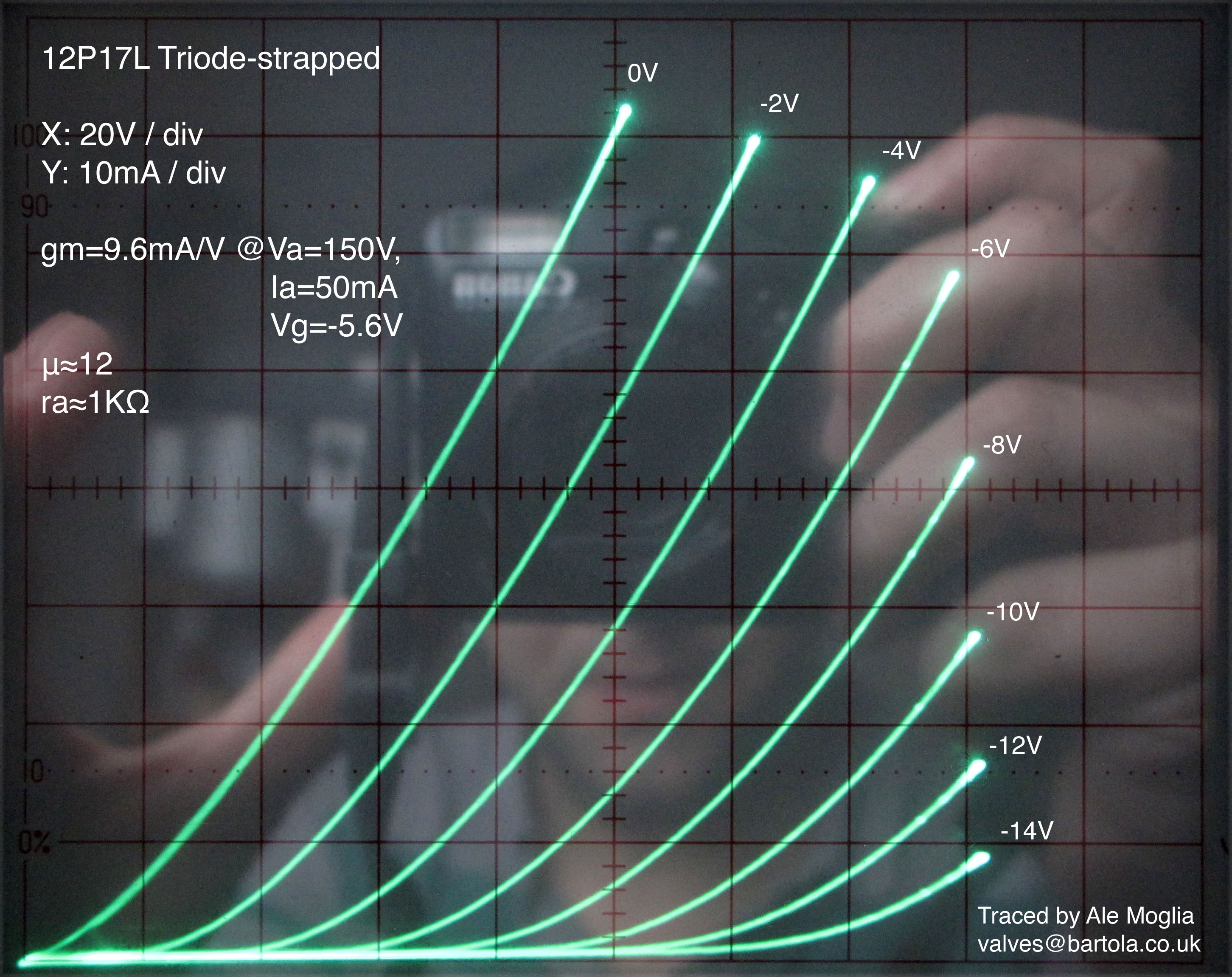
I traced these time ago, the curves are superb as well. Can't find which post was, but if you want to, let me know and can retrace the anode characteristic curves in triode and you can estimate graphically the anode resistance.
Cheers, Ale
The internal resistance 12P17L ~1,7 komI want to try, but never seem to find this lamp (12P17L) the internal resistance, which would calculate the output transformer
I traced these time ago, the curves are superb as well. Can't find which post was, but if you want to, let me know and can retrace the anode characteristic curves in triode and you can estimate graphically the anode resistance.
Cheers, Ale
Hi Ale;
do you have them? I expect them to be almost like for 4P1L except on higher negative voltages on control grid.

Thank you Svetlana. It would be nice to see the whole picture, including positive voltages on the control grid, to be sure that it is very close to 4P1L.
Hi Ale;
do you have them? I expect them to be almost like for 4P1L except on higher negative voltages on control grid.
There you are, if you still need me to trace them I can try and do it over the weekend. Let me know...
Thanks
Ale
There you are, if you still need me to trace them I can try and do it over the weekend. Let me know...
Thank you Ale; it would be nice to know! And other DIYers will be grateful as well.
Can you also trace curves in right handed mode (all grids together)?
I was planning to trace them with g2 and g3 tied to anode, wasn't aware this is called right handed? So, what is the name when g3 is tied up to cathode?
My tracer has some limitations so I will do what I can....
Cheers,
Ale
My tracer has some limitations so I will do what I can....
Cheers,
Ale
I was planning to trace them with g2 and g3 tied to anode, wasn't aware this is called right handed? So, what is the name when g3 is tied up to cathode?
My tracer has some limitations so I will do what I can....
No, if to connect G2 and G3 to anode it will be left-handed (biased by negative G1 bias), but if to connect all 3 grids together it will be right-handed (needs positive bias).
When G3 is tied to cathode the name is Pentode with internally connected G3 to cathode. 🙂
However, if to connect G2 to anode it will act as triode.
When G3 is tied to cathode the name is Pentode with internally connected G3 to cathode. 🙂
However, if to connect G2 to anode it will act as triode.
thanks for the clarification! I was refering to the latter when said G3 connected to the cathode and g2 to the anode. Does this mode have a name?
My tracer is very limited in positive bias, so probably won't be able to get the curves wanted on that region...
Anatoliy,
Long day at work, so tried to do my best in the short time available for this.
I think I got a very nice set of curves (in left handed triode mode only) and a very accurate SPICE model:
12P17L curves and Spice model | Bartola Valves
Happy for someone to check this, test model and provide some feedback
Hope this is useful for the ones working with this great valve.
Cheers,
Ale
Thank you Ale;
it is very similar to 4P1L. I would expect very similar curves on positive g1 voltages as well.
it is very similar to 4P1L. I would expect very similar curves on positive g1 voltages as well.
indeed!Thank you Ale;
it is very similar to 4P1L. I would expect very similar curves on positive g1 voltages as well.
I wish I could trace positive curves! Need to redesign the grid driver circuit.
Have the supply available in the tracer, just need some help with the design....
THD at 50mA/Va=150V is not impressive: THD=0.35%@Vo=+22.22dBu.
However is very interesting to see that there is an H2 cancellation point around Ia=20mA and Vg=-2V producing THD as low as 0.013%!:
12P17L THD analysis | Bartola Valves
However is very interesting to see that there is an H2 cancellation point around Ia=20mA and Vg=-2V producing THD as low as 0.013%!:
12P17L THD analysis | Bartola Valves
Bigger cathode area, higher 2'nd order distortions. But easier to power filament.
Interesting. Didn't know that...
On a separate note, haven't found a triode more linear than 4P1L. 6e5P and 6C45 are very close in terms of linearity. As a reference, I got 0.003% at Vo=+22.22dBu (Ia=50mA and Vg=-7V in triode mode). Others measure 0.03% and above...
- Home
- Amplifiers
- Tubes / Valves
- One more 4P1L SE