According to section 7.5 of https://www.ti.com/document-viewer/lm317/datasheet the RMS output noise voltage of an LM317 is typically 0.003 % of the output voltage measured from 10 Hz to 10 kHz. Elvee's circuit has complete feedback, like a 1.25 V regulator with an LM317 would have, so the noise should be 0.003 % of 1.25 V, or 37.5 uV RMS, about -86.3 dBu, from 10 Hz to 10 kHz. If white noise dominates, that's about -83.3 dBu from 20 Hz to 20 kHz, or -85.2 dBu A-weighted.
Last edited:
![20240225_141925_HDR[1].jpg](/community/data/attachments/1185/1185902-002a2080e95ad114e49bd4a2cb98577b.jpg?hash=ACoggOla0R)
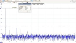
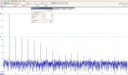
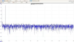
The noise and THD results are below.
Descriptions are in titles.
Setup is identical as schematic above. Nothing was changed.
Maybe I have done something wrong, or it is still something wrong with the HF behaviour of the circuit, as the circuit is distortion "free" only up to 500mVp.
Beyond this input amplitude, the harmonics rise up immediately and stay constant at around -45dBc to -50dBc.
I will appreciate your check and feedback.
I need SNR and THD up to 3Vp range, at minimum (best would be 5-6Vp) to function well in its Line Amp role.
P.S. I will remove now the 560Ohm load and replace it with something like 5K or 10K. Maybe the load (simulation of the Headphones, which is not the focus) is the problem.
Attachments
-
 LM317T_600mV_4096PTS_NotAveraged.jpg325.7 KB · Views: 72
 -
 LM317T_1000mV_4096PTS_NotAveraged.jpg331.9 KB · Views: 78
 -
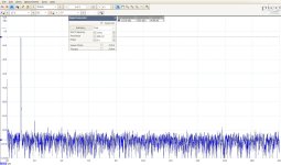 LM317T_500mV_4096PTS_NotAveraged.jpg323.9 KB · Views: 66
 -
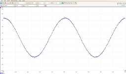 LM317T_Time_LP200KHz_10mV.jpg200.2 KB · Views: 63
 -
 LM317T_NoiseFloor_4096PTS_NotAveraged.jpg297.8 KB · Views: 62
 -
 LM317T_NoiseFloor_4096PTS_averaged.jpg190.7 KB · Views: 69
Did change the load with 10K and no change. Same distortions behaviour.
Will try change the 317T with a 317HV.
Will try change the 317T with a 317HV.
is the DS expectations matching well with my measurements?According to section 7.5 of https://www.ti.com/document-viewer/lm317/datasheet the RMS output noise voltage of an LM317 is typically 0.003 % of the output voltage measured from 10 Hz to 10 kHz. Elvee's circuit has complete feedback, like a 1.25 V regulator with an LM317 would have, so the noise should be 0.003 % of 1.25 V, or 37.5 uV RMS, about -86.3 dBu, from 10 Hz to 10 kHz. If white noise dominates, that's about -83.3 dBu from 20 Hz to 20 kHz, or -85.2 dBu A-weighted.
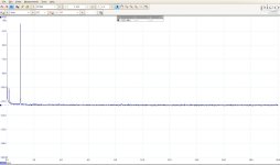
I see noise floor down to -113dBu for less than 500mVp input.
No idea, I don't know what the bin width is. It says 4096 points in the file names, but what is the sample rate?
sample rate is not a parameter that I can change in SW, so it is probably to be found in 4262's DS
I can measure the time mode (oscilloscope) with LP200KHz and additionally a filter of 20KHz, and obtain a Vrms value of the noise with known BW.
Indirectly I can then 'calibrate' the SA-mode and work out its time constant / i.e. sample rate and dead time combined.
What is the formula to use?
I can measure the time mode (oscilloscope) with LP200KHz and additionally a filter of 20KHz, and obtain a Vrms value of the noise with known BW.
Indirectly I can then 'calibrate' the SA-mode and work out its time constant / i.e. sample rate and dead time combined.
What is the formula to use?
Not necessarily: a regulator is much more complex than a single transistor and is more susceptible to generate noise. Marcel quoted the DS specification, which is relatively pessimistic compared to reality, but in the denoizator thread, there are actual measurements.Measuring THDs so low, means to me that I expect SNR is also equally low. Am I right?
I may make a noise measurement on this buffer too
I have measured the amplifier (with the input shorted). In a 10Hz to 10kHz range, the total rms noise is 15µV. For 10Hz to 100kHz, this becomes 37µV rms
it does look extremely dirty. I was equally confused, as in such condition I would not expect to see -113dBu noise floor.The time-domain waveform looks extremely noisy. Is it real or just a display artifact?
Sadly, not an artifact. Surely has an explanation, but I have no idea how to interpret it. First time when this instrument puts me a question like this.
That's why I attached it additional to the freq. plots. Maybe you can tell more.
The emmiter follower was clean also on time domain, not just in frequency. Same for all my projects so far.
And 500 times the noise of a transistor follower in the same conditions.....
That's hardly surprising considering that it has a built-in bandgap reference. Bandgap references are notoriously noisy, the very first one excepted.
Totally OT: I wonder if a new LED laser diode shinning into a good photodiode would improve the reference noise.That's hardly surprising considering that it has a built-in bandgap reference. Bandgap references are notoriously noisy, the very first one excepted.
Bandgap's noise can be filtered, by lasing conditions🙂 Probably //surely// the amplitude noise will still be there on the source side, and the photodiode efficiency being a statistic parameter will add fundamental noise too, but both are integrative in nature so a filter can be built for it. Then the reverse current and the Front End. Still... maybe better than a pure band gap reference.
The output voltage of the LM317 is the voltage on its ADJ pin plus the voltage from its internal bandgap reference. I don't see how you could filter that in Elvee's circuit other than by putting a big filter after the amplifier that also suppresses the signal, which would make it rather useless.
Sorry for me defocusing the topic.
In my sunday evening's fantasy it was a LM317 without the internal bandgap reference, or at least not as is made today.
The changed one, either can have an internal Laser-Photodiode reference or with pin for external reference (which probably such device should already exist).
So, filtering should occur in the reference, not outside of it, to provide a more precise (more noiseless) output.
German go eat.

I don't understand how the distortion appears: on my own setup, I made tests at 8Vpp out, and there was still some margin available.
Isn't it an issue with the SA configuration? Maybe the input is driven into overload, and you need to insert an attenuator, internal or external?
I hope your SA doesn't have a 50ohm input, because that would cause overload, for sure
Isn't it an issue with the SA configuration? Maybe the input is driven into overload, and you need to insert an attenuator, internal or external?
I hope your SA doesn't have a 50ohm input, because that would cause overload, for sure
- Home
- Source & Line
- Analog Line Level
- One BJT line amp/buffer