Ok i found the part number is TIPD136
https://www.ti.com/tool/TIPD136
However I cannot find the price
In case i will use opamps the idea is to purchase one of those empty boards sold for the NE5534
There is also a thread in this site talking about it I will read it carefully
https://www.diyaudio.com/community/threads/ti-active-volume-control-board-tipd136.269592/
thanks for the hint
The ready built demonstration (reference) boards from TI are usually expensive, no matter what.
The price difference between demo boards and self made boards is often a factor 10x or more.
But the last one requires more of your work and experience.
The price difference between demo boards and self made boards is often a factor 10x or more.
But the last one requires more of your work and experience.
good idea and approach. Go for it.In case i will use opamps the idea is to purchase one of those empty boards sold for the NE5534

You were wanting a circuit that could simultaneously drive line outputs and headphones. Headphones are generally somewhat low impedance, with brands like Grado and Audio Technica having impedances in the range of 35-38 ohms, and Sennheisers having an impedances as high as 150 ohms.
Headphones are generally rated for a max input power of 200 mW. This is likely ear-shattering volume, so let's instead specify the input power as a more modest 100mW.
To get the RMS current necessary for for drive at this power level, use the usual formula P = i^2 R. For 100mW RMS at 38 ohms impedance, this results in an RMS current of around 50 mA. This needs to be multiplied by 1.4 to satisfy a peak sine wave output without clipping, so you get a requirement of 71 mA peak current. For 150 ohms impedance, the requisite currents are 25 mA RMS and 36 mA peak. This looks really high, but remember, you are driving a relatively low impedance. Do the numbers....
In the interest of having low distortion, you need to run a bias current of several times the required peak output current. This is why I presented a circuit using MOSFETs in a TO-220 package that could be used with an appropriate heat sink, in order to handle the required power dissipation without self-destruction. A TO-92 device would not have a prayer of handling the required power dissipation without destroying itself. The output coupling cap necessary for decent bass reproduction will be dictated by the impedance of the headphones in question, and can be calculated using the equation F = 1/6.28*C (farads)*R.
thank you for looking into this.
I use the same headphones as specified originally on Revox: 600Ohms
Indeed, 100mW is more than enough power. Hence I=18mAp
The LM317 did the trick, but with some distortions at max Vol. Since the headphones were optional (still are, just for a direct low level monitoring) I serialized an additional 1.2K to the headphones. New total is 1.8K load (when connected and max Vol). For LM317 this solved the puzzle, as this is preloaded with 512Ohm: total current flowing is slightly below 20mA without headphones and probably 25mA with them connected (15mW). Anyhow, for safety I put 0.5W resistors on preloads and the thermals are okay.
The new look into 1XBJT vs 2XBJT is just in case there will be objections on some minute aspects of tonality for LM317. Here as well, the 15mW headphones load (if any - as they are wished but still hardly a requirement) will be sufficient.
The board redesign from scratch or an invasive repurposing (traces cut or new holes) is not the goal here. I must use the previous lineamp PCB. Your proposal contains 3xBJT/MOSFET. Too much - not possible, as reserving 1xBJT for other functions is mandatory. Therefore, I am stuck with maximum 2xBJTs/MOSFETs.
The 2xNPN circuit sent by @ginetto61 is actually similar to LM317 + 1BJT (constant current) instead of R preload proposed previously in this thread.
This could be "the sonic alternative", but I fail to see how: as the distortions in the line will be the same as for LM317, but with less power (no chance for headphones). Only better noise (btw. MOSFETs don't have too much 1/f noise?).
My stomach hunch tells me to look for CF-TCA topologies with 1x or 2x BJTs, if they exist at all. I even started a separate thread on this question. No reply so far.
If you are stuck with just 2 BJTS or TO-220 mosfets. You could always use a depletion mode mosfet for a current source load on the topside mosfet. One of my go-to devices for this purpose is the IXYS IXTP08N50D2, which is a 500V TO-220 device with an 800mA min IDSS. I use this device all the time as a current source to drive low impedance shunt regulator supplies for my preamp projects. The device is currently in stock at Digi-Key, and is not all that horribly pricey. When I have some time, I'll gin up a suitable circuit that will have enough bias current to drive your 500 ohm headphones without difficulty. You could probably get by with using the DN2535N5 from Microchip, which is a TO-220 device that has a min IDSS of 150 mA. The series resistor you mention using with your headphones probably got you out of a jam with respect to available bias current in your LM317 circuit.
Since your headphones are 500 ohms, I could likely come up with something that could easily be constructed on a bit of perf board using a pair of Zetex/Diodes, Inc. E-line mosfets ( the ZVN3306A comes to mind) and a single TO-92 NPN transistor for each channel. Having a 500 ohm load really reduces the need for a lot of bias current to drive things. It also greatly reduces the size of output coupling cap needed for adequate bass response.
Since your headphones are 500 ohms, I could likely come up with something that could easily be constructed on a bit of perf board using a pair of Zetex/Diodes, Inc. E-line mosfets ( the ZVN3306A comes to mind) and a single TO-92 NPN transistor for each channel. Having a 500 ohm load really reduces the need for a lot of bias current to drive things. It also greatly reduces the size of output coupling cap needed for adequate bass response.
Last edited:
Why not just configure another LM317 as a current source?

Nice and simple with good specs. You can even get them in TO-92 if your careful of dissipation.
Nice and simple with good specs. You can even get them in TO-92 if your careful of dissipation.
A TO-92 317 won't cut it for power dissipation. The E-line package device I had in mind will dissipate a half watt without breaking a sweat, more if you glue them to a heat sink. I'll know more about the necessary bias current when I can get to a copy of PSpice and run the numbers. 20mA bias current is needed just to avoid clipping with a 500 ohm load. More will be needed to to reduce distortion - I'll be finding out how much. Maybe a lower Vcc supply will be needed to cut the power dissipation down.
True.20mA bias current is needed just to avoid clipping with a 500 ohm load. More will be needed to to reduce distortion
However I did step back because the HF (not really HF, just outside 100KHz up to 2MHz) somehow show trains of noise pulses. No idea why. Maybe too low PSRR at those frequencies. The Arcam's cheap PS or my handy (4m distance) are the main suspects as usual.
Changing the snubber did not help.
The schematic used was the one proposed here. Keeping simple.
Power supply and distribution in Revox A77 is not great. This keeps me in check when thinking MOSFETs.
I have some stock of IRF620 from a previous project.
If I will consider MOSFETs and redesign from scratch I am tempted to use the unused +/- 35VAC supply specifically for this board. Maybe a nice CS+shunt will do better. When or if I will do it... considering the 1/f noise in tape is already a pretty serious annoyance.
Yes, larger supply rails is an easy way to bring down distortion but isn't that far to much voltage given that its a line level buffer?
you mean the Kenwood one mentioned above with regulated +/-50V rails (from 2x70Vac!)?
Yes, it is a bit extreme but I think this is already typical for them and others from Japan.
Let's appreciate that they did not went up to regulated +/-120V or +/-180V 🙂
Yes, it is a bit extreme but I think this is already typical for them and others from Japan.
Let's appreciate that they did not went up to regulated +/-120V or +/-180V 🙂
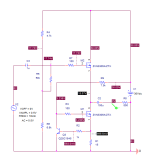
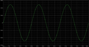
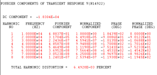
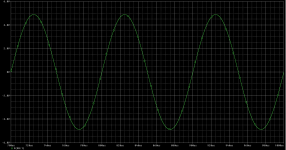
Here is the version using the ZVN3306A mosfet from Zetex/Diodes, Inc. Distortion is not too shabby, and dissipation for the mosfets is ~0.55W. These would probably run at a little over 70C without a heat sink, but you could glue the part to a standard TO-220 screw-on heat sink for some dissipation relief. I would recommend using a filled epoxy like JB Weld for better thermal transfer to the heat sink. Degrease the heat sink using 91% IPA before gluing the part down for better adhesion.
Attachments
Off topic: a flexible silicone glue won't be more suitable?
The filled epoxy will be stiffer and still way more expanding than metals. I wonder: it won't hold many cycles ?
Besides the fact that filled epoxies are not as fluid anymore, hence thicker layer - less recommended for thermal transfer.
The flexible silicone will be both super thin... and flexible. It might beat the filled epoxies.
Do you have any info&advice in this direction?
One can even try to mix the silicone glue with BN3 superfine powder, or even better with non-flaky fillers.
Virgin silicone will be more pliable than epoxy, however the thermal conductivity won't be very much superior.
Once you have added enough heat-conducting fillers, the flexibility is mostly gone.
I have made a number of tests on many materials: https://www.diyaudio.com/community/threads/a-thermal-ohmmeter.322079/post-5419745
An interesting and informative journey
Once you have added enough heat-conducting fillers, the flexibility is mostly gone.
I have made a number of tests on many materials: https://www.diyaudio.com/community/threads/a-thermal-ohmmeter.322079/post-5419745
An interesting and informative journey
True but there is a difference. Filled epoxies can get 80-90D while filled silicones remain a A.Once you have added enough heat-conducting fillers, the flexibility is mostly gone.
The 60deg cycling of 90D can undo adhesion. Local loss of adhesion triggers a spiral leading into catastrophic failure. The A will stay glued and stable.
I did not meant a virgin silicone, but something more expensive suitable for heavy duty ultrasonic applications...
Sincere Congrats! Great effort and true high quality hobby work.I have made a number of tests on many materials: https://www.diyaudio.com/community/threads/a-thermal-ohmmeter.322079/post-5419745
An interesting and informative journey
I did differently (not published): transient - not steady state.

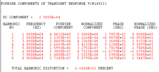
I am sorry, do I read correctly H2 at -64dB , In 5V and 500Ohm?
These simulation results are not at the level which I need. The LM317 can do much better at the same load or even stronger ones.
These simulation results are not at the level which I need. The LM317 can do much better at the same load or even stronger ones.
why CS role be done by a second 317? Any advantages vs same role by resistor or BJT or FET?Why not just configure another LM317 as a current source?
Reminder... so far no PM or explanation in the thread.Please PM me to learn what the ..., "White buffer", "LV's tandem", "regenerative bias", "diode distortion cancellation" ideas are.
https://www.diyaudio.com/community/threads/one-bjt-line-amp-buffer.409364/post-7612203
Many thanks in advance for your kind effort.
- Home
- Source & Line
- Analog Line Level
- One BJT line amp/buffer