I think your results are more dependable than mine As i said i usually place a load of 5K at the output But i am getting strange resultsThe headphones have Prio-2. I can drop this requirement.
What I am concerned in your circuit above, is that good THD requires 22Kload. The standard 10K load is already worse than LM317.
If good THD is stable until 5K, it would be even nicer for me.
For instance i have simulated a preamp of which i have the specs The specs are quite better than the results at sim Clearly i am doing something wrong
However in general it seems that the CFP when well used can be a pretty decent unity gain buffer It was very popular in good preamps in late '70s (vintage era i know The world has progressed since then)
If one wants some Vgain the THD increases clearly
Let me know if you find something great and i will build it myself as well As you say the LM317 is very tempting Difficult to find another circuit so simple and still so good I would have never imagined that a voltage regulator can work as buffer Bad thing ignorance
Thank you very much again and good luck 🤓👍
In a silly play mode, I have tried to modify your circuit into a Current Feedback TCA with BJTs, but without success in this direction.
However, after a few 'optimizations' it turned out as a Buffer with variable attenuation and it has a very nice THD 0.0027% in full range of attenuation (for loads above 10K).
More, at +12dBV it has THD of <0.01%. Wow!
Also, it accepts loads down to 5K with just 0.02% THD sacrifice.
I don't know who cares about this, I'll just post it.
Maybe the SNR of a simple voltage divider has a better SNR below 1KHz, but apparently the SNR of this active attenuator is better by 5dB above 1KHz.
Personally I was looking a long time for such toy. Still, maybe I did some mistakes. If anyone sees them, please drop a line.
(...and I am still looking for a basic Current Feedback TCA topology with simple BJTs... no Opamps)

Hi sorry for the belated reply Then we are at least two playing in silly mode 😉In a silly play mode,
The discovery of these sim SWs has really excited me And i do not even know how to use them properly 😵
very very interesting and thank you for sharing your great results Clearly the requirements to drive a power amp and an headphone are very differentI have tried to modify your circuit into a Current Feedback TCA with BJTs, but without success in this direction.
However, after a few 'optimizations' it turned out as a Buffer with variable attenuation and it has a very nice THD 0.0027% in full range of attenuation (for loads above 10K).
More, at +12dBV it has THD of <0.01%. Wow!
Also, it accepts loads down to 5K with just 0.02% THD sacrifice.
I don't know who cares about this, I'll just post it.
Maybe the SNR of a simple voltage divider has a better SNR below 1KHz, but apparently the SNR of this active attenuator is better by 5dB above 1KHz.
Personally I was looking a long time for such toy. Still, maybe I did some mistakes. If anyone sees them, please drop a line.
(...and I am still looking for a basic Current Feedback TCA topology with simple BJTs... no Opamps)
View attachment 1313307
I see that lowering the load the performance collapse And also increasing gain can reduce but less the THD+noise
I cant sim your schematic because i do not have the used bjts models But i am sure that with try and see changes very decent performance can be obtained from the circuit
If you will ever build it let me know your impressions
Thanks a lot again and have a nice day
gino 🙂👍
Tina has them natively. Just download, it is free.I cant sim your schematic because i do not have the used bjts models
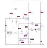
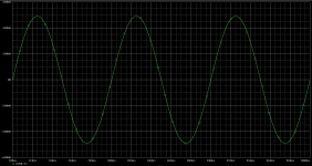
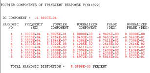
Though a touch more complex, this circuit is more likely to deliver what the original poster actually needs. The mosfets are rather hotly biased, so each mosfet will need an appropriate heat sink. The circuit is a classic current source loaded source follower using IRF510 mosfets for both the input and current source positions. I used the 510s because of their relatively small input capacitance, making them easier to drive. If a pot is placed in front of the input mosfet, the added impedance will likely slow down the response. Attached are the circuit, the output waveform and the sim distortion profile.
Attachments
Hi thanks again I will have a look But i am really out of my possibilities I feel like a boat in the woodsTina has them natively. Just download, it is free.
Without help for instance in settings i would not have been able to get decent results They are SWs for people who knows the discipline
I will have a look at Tina anyway Is she blonde ? 😏
Last edited:
@wrenchone To be fair, the original post asked for 1xBJT solution to requirements. Solved stellar by LM317.
Later, I asked if 2xBJTs can be an alternative to LM317. This is where we are right now.
I am not yet to 3x BJTs (J-FETs or MOS-FET included), and I will most probably will not be.
I believe your statements and appreciate your proposal, but I won't build it soon.
Getting back to 2xNPN modified by me (Post #242), I made its first build tonight using BC550-B:
- buffer function confirmed as expected
- variable attenuation not confirmed. Dead stable, no matter what P1 setting is. I must hunt for my mistakes though.
- SNR (rms) measured is better than 116dB (not A-scaled)
- harmonics: measured H2 <-100dB if P1 is low, and ca -74dB if P1 is high. Expectations were H2 to be around -100dB, but independent of P1 setting.
I always run Tina in its default settings.Without help for instance in settings i would not have been able to get decent results
Not 'my choice'. I am simply constrained by an existing PCB which I want to repurpose&improve it.That's your choice....
More, I can add bridges, but I don't want to cut traces or drill holes. Not invasive work.
I start from 3xNPN and want to land into 2xfunctions by 1xBJT or by 1xBJT + 2xBJT. That's pretty efficient in filtering my options.
Funny, even LTSpice tells this should be a variable attenuator.variable attenuation not confirmed. Dead stable, no matter what P1 setting is. I must hunt for my mistakes though.
Maybe I bumped the BJTs by mistake, somehow...
the BJTs were bumped. replacing them fixed the problem
@ginetto61 for reference, from where you got the 2xNPN buffer?
@ginetto61 for reference, from where you got the 2xNPN buffer?
I really apologize I didn't know the circuit was faulty I just played around a bit changing the resistors at random and checking how it changed at fft
Let's say I started from the bottom I'm missing the basics
For example, I don't know if there is an optimal working point for a transistor but I think so because by increasing bias and voltage the performance often improves. But I'm making attempts without criteria
For example, I take schematics of commercial appliances and do the fft for curiosity
For this schematic i just put two bjts one on top of the other and add some resistors for biasing them
It is like the B1 buffer but with bjts Then i changed resistors and saw how the THD spectrum was changing
I am interested in unity gain buffers mostly for a future active volume control
Let me know the schema you will end with and i will see what i get for the THD so that we can compare the curves
You are doing a great job indeed Congratulations
Good morning What i actually meant is that i did not build and tested it@ginetto61 for reference, from where you got the 2xNPN buffer?
I have just tried to optimize the circuit on the basis of the simulation and the result of the fft
I have tried to reach a low THD and stop
I have checked the dissipation of the bjts and is not that high I hope there will be no problem with the prototype
I am in a middle of a moving to a new house and i am seriously difficulties
After i will have finished the moving i will dedicate more seriously to the search of a good voltage follower circuit
I like the idea of having a great attenuator followed by a very clean (i.e. low in THD+noise) buffer
Then i will be able to try different power amp options in the best conditions If you see what i mean
Let me know how your project will end
Best wishes and have a spice day ... i mean a nice day 🤓👍
I never said this. Where do you read it?I really apologize I didn't know the circuit was faulty
Then you have more talent than me, or much more luckier. I thought your proposal was inspired from a product, web site or a book. Was it?For this schematic i just put two bjts one on top of the other and add some resistors for biasing them
Then in 2024 better do this or similar: https://www.ti.com/lit/pdf/tidu034I am interested in unity gain buffers mostly for a future active volume control
I am here stuck with BJTs by force of necessity, not by choice, skills or talent.
But truth be said, I am also curious as I have avoided BJTs for too long time.
Hi thanks for the link
I see a Zin of 50ohm ?
However this is a product for pros so I guess quite expensive
Speaking of opamps like I have already advised is very difficult to achieve the performance of the best ones with discretes
Most of the manufacturers of high end equipment have switched to opamps
I am trying to simulate some but I got weird results
I have to study more
Where do you see it? They mean source impedance and is written 20 Ohms.I see a Zin of 50ohm ?
Be serious. This circuit is definitely less expensive than postage, train ticket or a bottle of wine. In addition the simulation file is there.However this is a product for pros so I guess quite expensive
- Home
- Source & Line
- Analog Line Level
- One BJT line amp/buffer