keyne said:the transformer needs to cope with 800mA DC - no go with a mains trannie. unless you have another winding and put a compensating current through this. (but then of course you have more active devices), yes like in schematic no. 3 on bonavolta's page. i think that looks like a very interesting amp...
transformer coupled transistor amps are rare..
my new preamp has an output transformer..
so why not a nice efficient SE amp with tx coupling for my horns..
regards
keyne
How about putting a cap in series with the output transformer primary, and in parallel run a low-resistance choke from supply to the drain? That would let you use a standard power toroid and a choke, no extra devices?
Jan Didden
Hey Jan,
what you describe is "parafeed" in the valve world.
the coupling C can be made smaller than without a step-down transformer.
i think this is interesting for my horn setup which only has to do 60Hz + . So i don't need to massively oversize the transformer to cope with low bass. This might lead to better HF characteristics of the transformer.
regards,
keyne
Have you looked at this?
http://www.tubecad.com/page11.html
http://www.tubecad.com/page12.html
I do not know if any of these amps have alredy been build and listened to - but well worth a try if somebody can calculate (and make...) suitable chokes.
Pathos is using the "inpol" circuit for a long time, the output section is a follower. The schematic was posted here before.
Klaus
Attachments
tom-vdl: That schematic you posted is pretty much the same as I have in mind. What would happen if we put a zener diode across that 47uF cap to stabilize the bias voltage? I know that it is an active device, but it wouldn´t be directly in the signal path.
And by the way I don´t see any feedback, you must havea log of gain in that circuit?
lohk: Choke loaded source followers are excellent output stages in my opinion but the have one major drawback: they need a separate gainstage.
And by the way I don´t see any feedback, you must havea log of gain in that circuit?
lohk: Choke loaded source followers are excellent output stages in my opinion but the have one major drawback: they need a separate gainstage.
keyne said:Hey Jan,
what you describe is "parafeed" in the valve world.
the coupling C can be made smaller than without a step-down transformer.
i think this is interesting for my horn setup which only has to do 60Hz + . So i don't need to massively oversize the transformer to cope with low bass. This might lead to better HF characteristics of the transformer.
regards,
keyne
So I invented parafeed?? Again?? What the heck!😉
Jan Didden
Looked, yes
Read them thouroghly, no. Shall do it.
Buffers with voltage gain?
Sound weird, but why not if it works?
Read them thouroghly, no. Shall do it.
Buffers with voltage gain?
Sound weird, but why not if it works?
Fuling said:And by the way I don´t see any feedback, you must havea log of gain in that circuit?
What about the 0.33 ohm source resistor?
se
Ah, have a look at the last topology on
http://www.tubecad.com/page18.html
That looks like something!
http://www.tubecad.com/page18.html
That looks like something!
Fuling said:Ah, have a look at the last topology on
http://www.tubecad.com/page18.html
That looks like something!
Yeah, a mess. 🙂
se
Fuling said:A mess, why?
Oh, just that MOSFETs are claimed to allow much simpler circuits. But here you've got half a dozen parts before you even get to the MOSFET.
se
Well, half a dozen ain´t much...
I don´t expect to build an amp with one active and no passive components per channel🙂
Yet to see if it really works in a real world circuit or if it´s just a bright theory.
I don´t expect to build an amp with one active and no passive components per channel🙂
Yet to see if it really works in a real world circuit or if it´s just a bright theory.
Fuling said:Well, half a dozen ain´t much...
I don´t expect to build an amp with one active and no passive components per channel🙂
Hehehe.
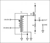
Well I've never really looked at MOSFETs in depth, but why couldn't something like this work? Just four parts.
Attachments
Fuling,
about the zener diode:
That will take care of drift caused by any variations in the mains voltage. However, you will have to replace the 250k pot by a normal resistor and the 390k resistor by a pot else it is not possible to set the quiescence current. I have thought about using a zener as you suggested, but I would rather have a solution that will take care of the thermal drift as well.
About gain:
As Steve Eddy pointed out there is a source resistor and that makes the gain of the amp approximately RL/0.33 where RL is the speaker load. As a speaker is a frequency dependent load gain will normally vary with frequency. Fortunately I have loudspeakers with a quite flat impedance curve.
Tom van der Laan
P.S. Just some information. The cutoff frequency for a given load and inductance is given by: Fc = RL / (2*PI*L)
Steve: That is ultimate simplicity!
Unfortunately stepup transformers tends to have crappy frequency response, at least if the ratio is bigger than 1:3 or something like that.
Tom: Current feedback, then?
What about a slightly higher value on that source resistor, that should take care of the thermal drift, right? Of course it would lower the gain, but maybe not too much?
Fuling said:Steve: That is ultimate simplicity!
Unfortunately stepup transformers tends to have crappy frequency response, at least if the ratio is bigger than 1:3 or something like that.
Not if they're loaded properly. The Jensen JT-13K7-A which is a 1:5 step-up has a flat response across its bandwidth, which is from 0.9Hz to 120kHz.
se
Fuling,
About a bigger source resistor:
You are right about that. A larger resistor will reduce thermal drift and a bit of thermal drift is not a problem. Using a larger source resistor will also boost the output impedance. However in my case that might not be such bad thing as I have recently switched to open baffle speakers. The higher output impedance might give me a bit more low frequency response. I think I will try it this weekend.
I wished I had discovered these tubecad pages before. They are great. Just one thing that I was wondering about. How do they set the bias current. With the low DC resistance of the inductor I think the feedback network in the amps is not going to work properly (at least not for DC).
Tom
Fred:
...and a resistor as source load.
I never said it would be a good or even functional amp, but simple it would be...!
...and a resistor as source load.
I never said it would be a good or even functional amp, but simple it would be...!
- Status
- Not open for further replies.
- Home
- Amplifiers
- Solid State
- One (1!!) transistor clapping...