Thanks Ken.
- Module 1 - Matter, Energy, and Direct Current (Jun 2011)
- Module 2 - Alternating Current and Transformers (Mar 2012)
- Module 3 - Circuit Protection, Control, and Measurement (Feb 2013)
- Module 4 - Electrical Conductors, Wiring Techniques, and Schematic Reading (May 2013)
- Module 5 - Generators and Motors (Sep 2011)
- Module 6 - Electronic Emission, Tubes, and Power Supplies (Mar 2012)
- Module 7 - Solid-State Devices and Power Supplies (Aug 2012)
- Module 8 - Amplifiers (Feb 2013)
- Module 9 - Wave-Generation and Wave-Shaping Circuits (Jul 2012)
- Module 10 - Wave Propagation, Transmission Lines, and Antennas (Jul 2012)
- Module 11 - Microwave Principles (Feb 2012)
- Module 12 - Modulation (Jan 2012)
- Module 13 - Number Systems and Logic Circuits (Jan 2012)
- Module 14 - Inroduction to Microelectronics (Sep 2003)
- Module 15 - Principles of Synchros, Servos, and Gyros (Dec 2012)
- Module 16 - Test Equipment (Apr 2013)
- Module 17 - Radio-Frequency Communications Principles (Apr 2013)
- Module 18 - Radar Principles (Apr 2013)
- Module 19 - The Technician's Handbook (Jan 2004)
- Module 20 - Master Glossary (Jan 2004)
- Module 21 - Test Methods and Practices (May 2013)
- Module 22 - Digital Computing (May 2013)
- Module 23 - Magnetic Recording (May 2013)
- Module 24 - Fiber Optics (Jun 2014)
http://www.compatt.com/Tutorials/NEETS/NEETS.html
Much appreciated!
At this point, I believe it is important to remember that the previous info provides just the basics of design engineering.
Even when earning a degree, one has only the elementary tools, such as equations, understanding tube/ss parameters,
etc. These tools are necessary, along with physics etc for further research and development.
cheers
pos
Even when earning a degree, one has only the elementary tools, such as equations, understanding tube/ss parameters,
etc. These tools are necessary, along with physics etc for further research and development.
cheers
pos
At this point, I believe it is important to remember that the previous info provides just the basics of design engineering.
Even when earning a degree, one has only the elementary tools, such as equations, understanding tube/ss parameters,
etc. These tools are necessary, along with physics etc for further research and development.
cheers
pos
How true is this! One also has to try to solve basic problems supplied in a book about vacuum tube theory to get some feeling
how to calculate basic tube circuits. Like this one:
https://www.diyaudio.com/community/threads/on-line-tube-learning-for-newbies.38278/page-12
Just a humble contribution.
How true is this! One also has to try to solve basic problems supplied in a book about vacuum tube theory to get some feeling
how to calculate basic tube circuits. Like this one:
https://www.diyaudio.com/community/threads/on-line-tube-learning-for-newbies.38278/page-12
Just a humble contribution.
Yes, that is part of basic learning one learns in college classrooms. I could have explained more in my previous post.
An example of something learned after college.
I don't know if this has been mentioned earlier, but when two components in a system have pin 1 connected to the wall socket, there
is a connection between the signal ground to both components. As such, musical information/signal current not only returns via both
left and right interconnect shields, but also through the pin 1 wires from component to component. This tends to mix the channels
together. There is all sorts of negative ramifications.
I have to admit that Jneutron first brought this forth about a decade ago. So simple yet profound and never mentioned.
cheers
pos
Very good point about grounding. Although I have specific DC returns and don't use ground return it's still a good illustration of how loops through ground (and ground lifting) can kill you.
a basic way to test capacitor ESR using a oscilloscope and a square wave.
Measuring leakage can be done in the same using two sense resistors then use the 4 channels to provide two differentials.
Very good point about grounding. Although I have specific DC returns and don't use ground return it's still a good illustration of how loops through ground (and ground lifting) can kill you.
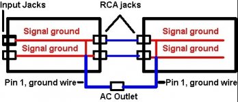
Well, I am not really discussing grounding per se. (For public's convenience I will try to be as simple as possible.)
I am discussing two components, each with its own internal power supply, Not one component with two separate chassis.
Attached is a simple schematic for the public's convenience.
I am Not discussing grounding. I am discussing a third musical signal current path from one component directly to
another via the pin 1 AC power wires of each component. The other two signal paths are through the
ic shields.
The AC outlet itself is only mentioned/shown because the two pin 1 wires present physical connections with
resistance present at the plug outlet junction.
(Notice I left out any reference to ground itself as it does not enter the picture concerning the musical signal path.)
Notice the two RCA Jacks labeled on each component. There are 2 ics connected between the jacks, each ic with an
inner conductor and a shield conductor.
The shield conductor of each ic is connected to the red signal common ground, (It does not make any difference
which red is labeled L and R signal ground.)
Now notice the two blue pin 1 ground wires connecting the AC outlet to the red signal common ground wires in
each component. Besides the two shields of the ics, the pin 1 wires also carry musical signal current from component
to component.
So what is the ratio of return signal current through the two shields and pin 1 wires?
The ratio of return musical signal current through the three paths is determined by the dc resistance, inductance
of the two shields and pin 1 wires, the frequencies involved, the connection resistances, width of component internal
foils/wires, solder resistance etc So it is not simply parallel and equal.
So what is the result. The result is that the actual stereo frequency response, the spacial information, and other
characteristics of the reproduction is affected by the above characteristics mentioned in the previous paragraph.
Stereo separation is affected.
If it is possible, attempt to create as much channel separation as possible.
cheers
pos
Attachments

Cable lacing looks so much nicer than cable zip ties. I've used it I'm a couple of amps I've built.
The roll of stuff I got was from the British post office, likely used in telephone exchanges.
The roll of stuff I've got is waxed cotton.
There is a reason NASA still do it this way on the Mars rovers.
The roll of stuff I got was from the British post office, likely used in telephone exchanges.
The roll of stuff I've got is waxed cotton.
There is a reason NASA still do it this way on the Mars rovers.
One has to be very careful with lacing or using zip ties as each wire in the bundle will "pickup" data/musical
information from adjacent wires. This will depend upon the impedance and distance involved, I have measured
distances of 1/2 inch between wires "picking up" a signal around -50db down from the source wire, with frequencies
as low as a couple of khz. This means the frequencies go much lower at -70 db etc.
Imagine what happens with a bundle of wires tightly knit.
cheers
pos
Typically, it's never been an issue for me as anything in the signal path is short and not going far unshielded, it's usually just a little wires around the power supply that I end up lacing and even then they are rather short runs.
I've had no issues with lacing but then I only lace power supply wiring and not signal wiring.

Andy.
Andy.
That is the point. By basic deduction, if there are no signal wires of any kind in the bundle, there is nothing
to worry about.
cheers
pos
to worry about.
cheers
pos
I also believe if they are at a much higher impedance between various tubes, that there is less risk of picking up noise.
I am not sure what you mean, but generally, stray signal pick up and noise are of lower amplitude as the impedances (Z)
of all stages are lowered.
With that said, if one is contemplating an additional stage to lower the output impedance of, say, a preamplifier, one has
to consider the possible benefits vs musical degradation caused by the additional added stage. Is it really necessary to lower
the output Z for the particular application/system.
It can get messy.
cheers
pos
Last edited:
Yes they do. -I found that out by touching the speaker terminals on an old radio. 😱i am quite sure that the fields coils on the fieldcoil type speakers double as psu chokes in some early radios...
Hello everybody,
I am prepared to build my first tube amp and my question is what kind of wire to use 1.from the trafo to the heater points /6.3 V, three tubes and 2, from the trafo to the anods - 250 v ?
Thanks in advance
I am prepared to build my first tube amp and my question is what kind of wire to use 1.from the trafo to the heater points /6.3 V, three tubes and 2, from the trafo to the anods - 250 v ?
Thanks in advance
Dear professional builders..
I'm going (wanting) to build my second tube amp after the first little one (an OTL headphone amp). This would be a simple good-old output transformer based class AB pushpull with KT88-KT150 tubes.
Need some advice/ideas if what I'm thinking of would work or not, cost and double part count is no issue.
My starting points were:
So all in all, I'd like to have as silent of an amp as possible (and besides: class A is not viable for me, so Class AB "fully-balanced" is the way to go).
Now when we talk about a fully balanced amplifier, it's actually a differential amplifier, right ? After the XLR input: normal signal is amplified, inverted signal is amplified and at the end they're bought together for an increase in overall power while cancelling out common mode noise. So basically even the internal common-mode noise(s) of an amp is cancelled out at the output if built well.
Now comes the trick: as I've seen, such amplifier topologies consist of 2 SE paths: both the normal and the inverted full signal is amplified in a single-ended fashion (mostly).
How about doing this in a push-pull configuration ?
So after the XLR input, first I would amplify normal signal via 2 stages in a push-pull fashion AND amplify the inverted signal via 2 stages in a push-pull fashion, the very same way.
Class AB push-pull means, the individual output devices conduct between 180-360° of their common input signal cycle with some overlap (depending on biasing) but anyway, I would first bring these "sinusoid halves" together for normal and inverted signals and then do the differential amplifier trick.
Not sure you get what I'm looking for - just in theory, no matter how crazy it sounds.
So, I see 2 ways to proceed with planning:
1) Since push-pull can be done without output transformer too, I would bring the pushpull pairs together (normal, inverted) and just THEN go to one big output transformer with the again-complete signals.
2) Since in usual designs push-pull operation is made with help of the output transformers's 3-tap primary winding, I would need 2 OT-s (1 for normal, 1 for inverted) and then again some trick after these transformers to unite the fully amplified normal and inverted signals to get 2x power while getting rid of noise.
Has somebody ever done such an idea (either option 1 or 2) and if yes, how is the end result ? Can it be achieved at all or does it sound just too crazy ?
Even if I would not do such a build I would still be interested in the theory if it would work to create from the XLR input 2 push-pull amplified opposite-signals and unite them in a differential amplifier's fashion - maybe with 1 transformer only.
So, mono, one side only, fully balanced, 2+2 output tubes.
I'm going (wanting) to build my second tube amp after the first little one (an OTL headphone amp). This would be a simple good-old output transformer based class AB pushpull with KT88-KT150 tubes.
Need some advice/ideas if what I'm thinking of would work or not, cost and double part count is no issue.
My starting points were:
- I want to maximize PSRR and common mode noise-cancellation, even within the amplifier
- input is balanced XLR, balanced amp topology would be great
- since most modern DAC-s come with a built-in preamplifier (op-amps, providing around 2Vrms/4Vrms RCA/XLR on the output) I don't want to go with classic 3-stage tube amp design and 150-500mV-ish input sensitivity.. I think the design would be very simple: 2 stages (driver and power stage), with an input sensitivity (XLR) of around 4Vrms. This might also further contribute to high SNR.
So all in all, I'd like to have as silent of an amp as possible (and besides: class A is not viable for me, so Class AB "fully-balanced" is the way to go).
Now when we talk about a fully balanced amplifier, it's actually a differential amplifier, right ? After the XLR input: normal signal is amplified, inverted signal is amplified and at the end they're bought together for an increase in overall power while cancelling out common mode noise. So basically even the internal common-mode noise(s) of an amp is cancelled out at the output if built well.
Now comes the trick: as I've seen, such amplifier topologies consist of 2 SE paths: both the normal and the inverted full signal is amplified in a single-ended fashion (mostly).
How about doing this in a push-pull configuration ?
So after the XLR input, first I would amplify normal signal via 2 stages in a push-pull fashion AND amplify the inverted signal via 2 stages in a push-pull fashion, the very same way.
Class AB push-pull means, the individual output devices conduct between 180-360° of their common input signal cycle with some overlap (depending on biasing) but anyway, I would first bring these "sinusoid halves" together for normal and inverted signals and then do the differential amplifier trick.
Not sure you get what I'm looking for - just in theory, no matter how crazy it sounds.
So, I see 2 ways to proceed with planning:
1) Since push-pull can be done without output transformer too, I would bring the pushpull pairs together (normal, inverted) and just THEN go to one big output transformer with the again-complete signals.
2) Since in usual designs push-pull operation is made with help of the output transformers's 3-tap primary winding, I would need 2 OT-s (1 for normal, 1 for inverted) and then again some trick after these transformers to unite the fully amplified normal and inverted signals to get 2x power while getting rid of noise.
Has somebody ever done such an idea (either option 1 or 2) and if yes, how is the end result ? Can it be achieved at all or does it sound just too crazy ?
Even if I would not do such a build I would still be interested in the theory if it would work to create from the XLR input 2 push-pull amplified opposite-signals and unite them in a differential amplifier's fashion - maybe with 1 transformer only.
So, mono, one side only, fully balanced, 2+2 output tubes.
- Home
- Amplifiers
- Tubes / Valves
- On Line Tube Learning for newbies....