That one is no so insightful. Only H2 is in-band - that is, withing the audio range of frequencies. H3 and above are out-of-band, where the loop gain, by design, rapidly falls with frequency. Because of that, THD 10k doesn't give you a meaningful picture beyond H2.Indeed, that's why I also model at 10kHz
There are a few potential problems with your schematic and PCB. It will probably work, but expect performance issues.I've been working on one!
Omicron construction, as mentioned before, is a single, all-through-hole, 78x108mm PCB that holds two amplification channels plus output filters and protection.

Using one board for two channels simplifies proper grounding, which is essential - and I cannot stress this enough - for the distortion performance of any amplifier with single-ended input. It also makes it easy to use a single power supply for both channels; I believe using one power transformer per channel of even a high-performance headphone amplifier is unnecessary (and costly).
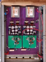
The power supply is on a separate, slightly larger (78x128mm), board:

Both boards are designed for commonly available parts, including axial 0.25W metal film resistors, radial NP0 or film capacitors (5mm lead spacing), an Omron G6A small-signal relay, Aavid 5310 board-level heatsinks, and so on. Two handmade components are theb toroidal air core inductors for the output filters - I will discuss them in a separate post. The connectors are Molex KK254 or similar, but the boards will happily accommodate 0.1" screw terminal blocks, other 0.1" connectors, or bare wire.
Most parts, including the output transistors allow, broad substitution. One that I do not recommend replacing is the 5532 opamp. In testing, it demonstrated best overall performance and is strongly recommended. Having said that, other opamps with GBW of 8 to 16 MHz (e.g. OPA2134) may work, but one needs to check for stability and clean clipping. Even the TL072 works well. although its lower gain shows in the slightly higher distortion:

Faster opamps (e.g. the 55MHz LM4562) require changes in the frequency compensation and are not recommended.
Using one board for two channels simplifies proper grounding, which is essential - and I cannot stress this enough - for the distortion performance of any amplifier with single-ended input. It also makes it easy to use a single power supply for both channels; I believe using one power transformer per channel of even a high-performance headphone amplifier is unnecessary (and costly).
The power supply is on a separate, slightly larger (78x128mm), board:
Both boards are designed for commonly available parts, including axial 0.25W metal film resistors, radial NP0 or film capacitors (5mm lead spacing), an Omron G6A small-signal relay, Aavid 5310 board-level heatsinks, and so on. Two handmade components are theb toroidal air core inductors for the output filters - I will discuss them in a separate post. The connectors are Molex KK254 or similar, but the boards will happily accommodate 0.1" screw terminal blocks, other 0.1" connectors, or bare wire.
Most parts, including the output transistors allow, broad substitution. One that I do not recommend replacing is the 5532 opamp. In testing, it demonstrated best overall performance and is strongly recommended. Having said that, other opamps with GBW of 8 to 16 MHz (e.g. OPA2134) may work, but one needs to check for stability and clean clipping. Even the TL072 works well. although its lower gain shows in the slightly higher distortion:
Faster opamps (e.g. the 55MHz LM4562) require changes in the frequency compensation and are not recommended.

Phenomenal work, thanks @alexcp. I'd very much like to try this... it aligns well with an old sketch design of mine on the 'future project pile' for a small-power amplifier.
But you are way ahead of me in developing, testing, delivering ... a working (nevermind: refined) implementation!
But you are way ahead of me in developing, testing, delivering ... a working (nevermind: refined) implementation!
Other than the grounding issue (which can be fixed with good technique), what issues are there?That one is no so insightful. Only H2 is in-band - that is, withing the audio range of frequencies. H3 and above are out-of-band, where the loop gain, by design, rapidly falls with frequency. Because of that, THD 10k doesn't give you a meaningful picture beyond H2.
There are a few potential problems with your schematic and PCB. It will probably work, but expect performance issues.
While this looks like great gear, I too am a bit puzzled and offput at the name 'Omicron'. Good god, why would you do this to yourself 😆!?
First, the input and output filters are not optional. You said you'd place the output filter someplace else, which is fine, but the input LPF is nowhere to be found.Other than the grounding issue (which can be fixed with good technique), what issues are there?
Second, the grounding issue is not going to be so simple to fix. In simulation, an inverting amplifier is quite simple:
What sometimes is not appreciated - and what I think your PCB does not quite take into account - is that both IN and OUT have the non-inverting input of the opamp as the reference.
Any voltage is measured between two points. Frequently, one of these points is the "ground". In simulation, the "global node 0", marked with the "GND" symbol, is always the same "ground". On a real PCB this is never the case - there is no single "ground". Each and every signal has its own reference.
As a suggestion, before sending the PCB to production, try building one channel on a breadboard - it has a relatively low NFB crossover frequency and no high-impedance nodes, so it will work fine - and getting low distortion numbers. I am sure there will be some frustration and a a few surprises.
BTW, measuring Omicron's distortion is a separate topic - I will post on it, too.
What is happening is an implementation of crossfeed as a textbook "inverting adder":I do not understand what is happening
with a slight twist that both inputs are first low pass filtered - one with a high corner frequency, the other, with low. See post #33 for additional details.
Last edited:
Have a look at how the inverting adder (aka the summing amplifier) works. There are many sources online; this one seems to be brief and to the point.why would you mix the input of one channel with output (feedback) from the other channel?
It seems that the output of one channel is fed back to the input of the other channel...
reducing channel separation in headphones (which can be very high) to a natural level observed in realistic listening environments.
Goodness me.... why would anyone do that??? There are so many other factors that would need to be perfectly executed before one should start thinking about reducing the channel separation... by introducing more feedback...by means of mixing the output of one channel - with the input of the other channel.
Sorry, that's not what is happening in a crossfeed. Please have a look at how the inverting adder (aka the summing amplifier) works.mixing the output of one channel - with the input of the other channel.
Remember, this is the entertainment industry, so the best way is to experience it firsthand. Plug in four resistors and two capacitors, give it a listen, and decide whether you like it or not. If not, you can always take the crossfeed out and listen as before.There are so many other factors that would need to be perfectly executed before one should start thinking
BTW same goes for Omicron as a whole - it is so simple and affordable there is no reason not to try it, e.g. as a summer or even a weekend project.
Should you trust your thinking more than your ears, read LInkwitz' article (also linked to in the aforementioned post #33) and, if you want more, the J.A.E.S. articles referenced in it.
Should you trust other people's ears more than your own, then perhaps these opinions will help:
I really like what the Xen passive crossfeed board does to the soundstage, so I’ll definately put it there on the next phase. This was just to compare these headamps to my existing ones without the xfeed.
I am grateful to EUVL and the XEN team for publishing both their crossfeed circuit and their listening impressions. Omicron's crossfeed circuit has the same frequency and phase response as the one from XEN, although the implementation is different.Every single one who have tried agrees. 🙂I really like what the Xen passive crossfeed board does to the soundstage,
Last edited:
I will!try building one channel on a breadboard
That's because it doesn't, just provides the pins to wire to. The ground pins at the output are just to separate the out pin from the voltage rails. The idea is to tie all the grounds together at a single point somewhere, and have them separated the rest of the way throughout the amp. Essentially, a star ground topology (greatly simplified diagram here):(snip)...I don't see how your PCB takes care of that even for one channel...(snip)...the input LPF is nowhere to be found.
Let me know if my theory is totally off though 🙂
I also had the input filter on the backplane board these modules are going on, just before the inputs, but I've added it to the board itself! I have also added a gain switch and bias control, in case I want the amp plugged into IEMs or running cooler during the summer. Adding the 1.5k in parallel sets the gain to around 1.08, close enough using standard E12 parts.
Last edited:
Wonderful circuit alex. I too like to have a go at my own layout of it.
Couple questions tho- what was the purpose of R2 4 6 19? Why multiple parallels?
Would you perhaps sim the optimal values for opa1641 1645 which i think are sota parts to play around with atm.
And lastly just an amateurish comment from me- i disagree with the redundancy you called out for dual mono topology. Its not so much the isolation between the channels and the transient smear thats theoritically there when a single regulator has to feed for 2 signals. With dual mono you have a chance for truly identical layout between the channels and the grounding for each channel can be further optimized because the routing need for the other channel is not there.
Pic is my dual mono headphone amp. Its modular and the module pinout allows for a textbook perfect opamp layout. The best output stage ive made for it so far has been the composite with diamond buffer (green boards). I feel that your circuit will perform even better. 👍
Attachments
I'd imagine you only populate some of them to adjust gain based on your preferencesthe purpose of R2 4 6 19? Why multiple parallels?
The problem with grounding is in the PCB artwork and is not fixable by external connections. Oh, and I just noticed your opamp is connected incorrectly.Let me know if my theory is totally off though 🙂
The purpose is to balance the impedances at the inverting and non-inverting inputs.what was the purpose of R2 4 6 19? Why multiple parallels?
See post #42 for opamps substitution.Would you perhaps sim the optimal values for opa1641 1645 which i think are sota parts to play around with atm.
Pretty looking boards. How is measured performance?textbook perfect opamp layout
I've been working on one!
I am happy to see you guys trying your hand at the board, but I cannot provide support for circuit modifications or custom PCBs, nor can I let anyone have the impression that I approve of any board other than our own - I do not. You are on your own there.I too like to have a go at my own layout of it.
Should there be interest in the PCB on which the results from post #11 were obtained, we can perhaps set up a group buy later this summer.
Thank you for the complement. I plan on taking it to a professional to have it measured. After that, will make a thread about the design.
Subjectively its as good as any commercial designs (sub $10k stuff) that its been compared against. The treble is particularly smooth/inoffensive whichs always a good sign.
Ah, its exact mirror of the inverting input resistors! Very clever!
Subjectively its as good as any commercial designs (sub $10k stuff) that its been compared against. The treble is particularly smooth/inoffensive whichs always a good sign.
.
The purpose is to balance the impedances at the inverting and non-inverting inputs.
Ah, its exact mirror of the inverting input resistors! Very clever!
Not everyone likes the sound of headphones, compared to the sound of loudspeakers in the open area in front of their head. Trying to bridge the gap (to allow headphones to mimic the speakers/open space) is to be commended, however, without having (as I mentioned previously) all factors catered for correctly, the result will be hit and miss to a great extent.
The only way this could work is to allow for fine-tuning of delays, corner frequencies, and amount of "final" crossfeed applied (consisting of the two prior elements...), to cater for different sources characteristics, headphones characteristics, and personal subjective expectations...even the interconnects, hook-up wiring and headphone cabling will influence the result.
All of these elements (above), in this particular circuit, will directly influence the frequencies/delays... .Not to mention that the grounding topology would need to be perfect.
In other words, the provision of crossfeed amount/frequency tuning should be a must. Also, selling the PCB only and letting DIY-er get "in there" with their own internal wiring, and layout of the common returns/grounding.... will definitely result in a failure. As you said, even the type of transformer will yield a different result.
So, maybe providing a full-blown, well-designed and constructed final product, with adequate adjustment options... could work?
Alas, manipulating the sound to achieve the stereo sound through the headphones (mimic the speakers in the open air; ears hearing left/right/mixed channels sound) using so many capacitors and added complexity... will inevitably cause a loss of natural harmonics balance (and this was not mentioned anywhere in this thread), which is also (I'd say even more) important, than fooling your head to think it is listening to the speakers, instead of headphones. It is more important now than 60 years ago when the idea came about.... because in the age of digital audio reproduction, hitting the harmonic balance and achieving natural sound reproduction... is so hard.
Last edited:
Before the quality of the PCB pattern, it seems that the inverting input and non-inverting input of OP-AMP are reversed in both the circuit diagram and the board.I also had the input filter on the backplane board these modules are going on, just before the inputs, but I've added it to the board itself! I have also added a gain switch and bias control, in case I want the amp plugged into IEMs or running cooler during the summer. Adding the 1.5k in parallel sets the gain to around 1.08, close enough using standard E12 parts.
View attachment 1066503
View attachment 1066509
- Home
- Amplifiers
- Headphone Systems
- Omicron, a compact headphone amp with -140dB distortion