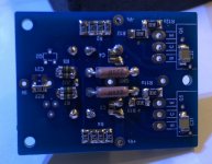
I’ve had some progress with the original version of the JLH headamp. The first channel is almost done, but I noticed a small problem with populating the Q1/Q2. The holes on the pcb are too small for the legs of TO-92 devices. What would be the easiest way to solder them? I was thinking of cutting the legs short and start with one leg and the continue with the others. Maybe it’s not wise to try to drill the holes bigger?
Attachments

Last edited:
They should be 0.6mm and normally large enough for TO92 ?
Easiest is to drill them larger (to say 0.7mm) but make sure you apply solder on both sides, especially on top.
The solder pads should be large enough and you just need to scrap off some solder resist.
Sorry for that,
Patrick
Easiest is to drill them larger (to say 0.7mm) but make sure you apply solder on both sides, especially on top.
The solder pads should be large enough and you just need to scrap off some solder resist.
Sorry for that,
Patrick
I rechecked the Gerber files and there was a conversion error.
So those holes were 0.4mm instead of 0.6mm.
The solder pads on the topis 1.5mm diameter in copper, and somewhat smaller in solder resist.
So you should have no problems drilling out to 0.7mm.
If necessary, a little bit of scrapping will certainly give you enough pad all round to solder.
I shall change Gerber and repost once you have built and tested OK.
No effect whatsoever on the XEN version using SOT23 devices.
Thx,
Patrick
I have finally done some listening tests with the original version of the JLH headamp circuit. I think it’s quite similar to Xen version of the JLH, but unfortunately I was not able to do direct comparison between them. Instead I compared to Salas DCG-3 with my Sennheiser HD-800 phones. In my opinion the JLH was better in terms of presence and vocals. Also the bass was surprisingly deep and controlled. All in all a very good headamp and easy to listen to.
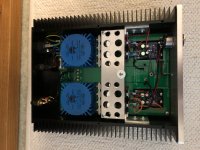
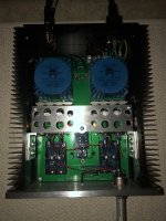
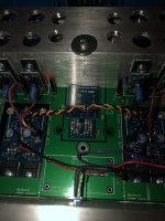
I had quite bad oscillation problems during the build, but luckily Patrick helped me out with his vast knowledge. Oscillations were tamed by placing a simple JFET buffer before the amp's input (the little green piece of proto board). Also small ceramic caps of 100pF were soldered between base and collector of the output devices. Too bad it required the buffer in front. Would have been nice to listen it directly in a more original form, but I suppose the buffer is quite transparent sonically.
I listened the amp in my newly finished case with the motherboard provided by forum member Algar_emi with Xen regs and all. I attached a couple of pics of the assembly. Still missing some parts for the SHPP protection board.
Next I will test the Xen version of JLH headamp by using this motherboard.
Attachments

Last edited:
I really like what the Xen passive crossfeed board does to the soundstage, so I’ll definately put it there on the next phase. This was just to compare these headamps to my existing ones without the xfeed.
> I really like what the Xen passive crossfeed board does to the soundstage,
Every single one who have tried agrees. 🙂
All credit to Dimtri Danyuk's original circuit for the inspiration towards the current passive version.
Patrick
Every single one who have tried agrees. 🙂
All credit to Dimtri Danyuk's original circuit for the inspiration towards the current passive version.
Patrick
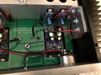
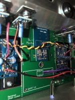
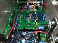
Oh wow...I just installed the Xen passive crossfeed board in front of the Xen JLH headphone amp board. The sound is stunning and the soundstage really opens up nicely away from your head. Now driving my Senn HD800s with ease...
Sorry about the poor pics but hopefully other builders get some ideas of how to mount the Xfeed board as an example.
Sorry about the poor pics but hopefully other builders get some ideas of how to mount the Xfeed board as an example.
Attachments
a) I guess you know that if you are not using a pot with the SMD XFD, you need to change the 12k resistors to 5.49k (= 12k // 10k pot).
b) For that particular layout, it is actually better to use the through hole version of the XFD, as seen here :
Current Drive for Headphones & The Super Linear Transconductance Amplifier
Just leave the JFET buffer unpopulated, or cut it off altogether, as I did.
But glad you like this one too, amongst all the others.
Patrick
In the link you posted for the F5-HA, R4,8 are 5.5k, as per the original design.
This was changed later in the passive version to 12k // 10k (of the pot) in the passive version.
The SMD PCB assumes you are using a pot, and hence 12k was specified.
If you are not using a pot, you should use 5.49k instead.
I'll let you find out the difference in Spice between the two.
The through hole version gives you a wider choice of resistors and capacitor types.
Patrick
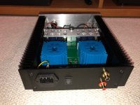
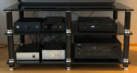
After a while I’m listening to the Xen version of the JLH headamp with my LCD2s. It sure feels like Zack de la Rocha is spitting to my face and I can here every detail of Tim Commerford’s bass while listening to Rage Against The Machine - Evil Empire. Hell of a headamp!
I attached a little family portrait of my rig in a brand new AV rack. In bottom row on the left is the guilty one this time.
I attached a little family portrait of my rig in a brand new AV rack. In bottom row on the left is the guilty one this time.
Attachments
Passive Danyuk Crossfeed
Someone wants to build the JLH HPA with our passive Danyuk crossfeed.
Since we stop all GB activities because of Corona, we cannot provide PCB.
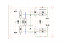
As a compromise, here is a layout that you can easily build with standard Vero boards.
Component values :
R1 = 11k
R2 = 5.6k when used alone; 12k when in parallel with a 10k pot.
R3 = 100k
R4 = 18k
R5 = 27k
C1 = 2.2n
C4 = 22n
We recommend Vishay Dale RN55 and WIMA FKP2 or MKP2.
Blue colour indicates jumper.
Patrick
.
Someone wants to build the JLH HPA with our passive Danyuk crossfeed.
Since we stop all GB activities because of Corona, we cannot provide PCB.
As a compromise, here is a layout that you can easily build with standard Vero boards.
Component values :
R1 = 11k
R2 = 5.6k when used alone; 12k when in parallel with a 10k pot.
R3 = 100k
R4 = 18k
R5 = 27k
C1 = 2.2n
C4 = 22n
We recommend Vishay Dale RN55 and WIMA FKP2 or MKP2.
Blue colour indicates jumper.
Patrick
.
Attachments
Hi Patrick,
I have a question. On the left channel of circuit, R1 is connected to R2 and R3 and R5.
On the right channel R1 is connected to R3 only.
Is it correct?
Thanks for sharing the layout.
Regards,
Tat
I have a question. On the left channel of circuit, R1 is connected to R2 and R3 and R5.
On the right channel R1 is connected to R3 only.
Is it correct?
Thanks for sharing the layout.
Regards,
Tat
- Home
- Amplifiers
- Headphone Systems
- The REAL John Linsley Hood Headphone Amplifier