Proper designed XO perhaps not but at the minimum a vintage speaker would have had a capacitor in series with the tweeter. There might even be a "rule of thumb" for what capacitor size to go with what cone diametre but I've not seen one but the smaller the diametre of the cone the higher the Fs and therefore the smaller the capacitor value.
I have a few old XO boards on my bench if you like I'll see what the values were on some Akai and Yamaha from the 70s
Your correct the tweeter has a 4uf capacitor hooked up to it. Yes, I am hazarding a guess that the original speaker didn't or had a very simple crossover perhaps one that didn't even take in consideration the frequency curve.
That capacitor IS the crossover on those speakers and generally all that was originally provided, older drivers often had a smooth top end that sounded fine run open with the natural roll-off. Sort of like Vifa P-13s in their characteristics.
That capacitor IS the crossover on those speakers and generally all that was originally provided, older drivers often had a smooth top end that sounded fine run open with the natural roll-off. Sort of like Vifa P-13s in their characteristics.
Okay so potentially, if both drivers can meet at a descent crossover point with a relatively flat frequency curve a second order crossover should work okay?
Lastly, DATS V2 does not provide us a CMS. No real big deal but I cannot enter parameters in Winisd without the CMS. Unibox works well I just want to double check my enclosure size before cutting wood. Any ideas? Have I missed something?
It doesn't work like that; you use the minimum amount of of components to give you the response you need, if your woofer already has a second order roll-off at the top end you change the response to a 4th order acoustic and other stuff if you add components for a second order electrical on the woofer. If you change the components in front of the tweeter it's possible that it won't integrate with the woofer the way if was manufactured to do but the tweeter might be able to handle more power. But not much point in the tweeter being able to handle more power if the woofer is limited to 20 or so watts which many of them were
You have just reached the limits of my very basic understanding of how these things work. You could post pictures of the woofer involved and the old box tho
You have just reached the limits of my very basic understanding of how these things work. You could post pictures of the woofer involved and the old box tho
It doesn't work like that; you use the minimum amount of of components to give you the response you need, if your woofer already has a second order roll-off at the top end you change the response to a 4th order acoustic and other stuff if you add components for a second order electrical on the woofer. If you change the components in front of the tweeter it's possible that it won't integrate with the woofer the way if was manufactured to do but the tweeter might be able to handle more power. But not much point in the tweeter being able to handle more power if the woofer is limited to 20 or so watts which many of them were
You have just reached the limits of my very basic understanding of how these things work. You could post pictures of the woofer involved and the old box tho
Using minimum amount of components I got, but totally confused about "if your woofer already has a second order roll-off at the top end you change the response to a 4th order acoustic" can you tell me more about this or send me a link that explains this more please? Never have come across this in forums.... I suppose this is important to take in consideration.
Also when you say it doesn't work that way, what do you mean exactly, like the amateur thinking of choosing a 2nd order crossover and using it? I will properly model a crossover in crossover modelling software but I am curious in worst case scenario seeing that it doesn't already have a crossover adding a simple crossover would do a simple job if on the off chance i can't manage the modelling.
Below is the woofers parameters.
27.89 Hz
8.30 Ohm
4.91
0.62
452.0 cm2
3.9 l
8.00 mm
0.76 mH
You don't need to do the last test if the tweeter has a closed back, it will not make any difference.
Try pm'ing 5thElement, he has a soft spot for old school paper tweeters.
Rob.
I do? 😱
I think you're getting me confused with system7 😎
Vas of 3.9 litres? Not possible on a woofer that big assuming it's a 10" with that area
Qms = 4.91?
Qes = 0.62?
How old is this woofer??? What's the voice coil diametre? Depth of the magnet and magnet plates? Because that is a big X-max in an old driver
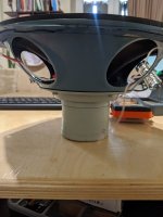
Pictures?
Parameters don't mean much without a waterfall plot from a sweep [ A stage I haven't reached yet] because without such information you don't know what the shape of the response is.
But experience with old woofers tells me that as the frequency gets higher the response slowly drops off and at a certain frequency that is often at a rate of 6 or 12 dB per octave. 6dB per octave is a first order response; 12dB per octave is a second order response, 18=3rd 24 = 4th etc
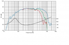
Look at the picture of the Frequency response of the little Vifa I use. That smooth roll-off at the top after 3000Hz is a classic second order response, the sound drops off at ~12dB per octave. If you add a coil at about 3k then that slope becomes a third order approximately, steeper in other words. May people think that a second order response give a better sound/ better integration. Now look at the drivers response below 300Hz, a classic approximation of a second rder slope, now if you put that little woofer in a closed box which in itself gets you a second order response the slope than doubles to a 4th order slope. One of the reasons I like the driver so much as a midrange, it is so easy to use.
May older drivers from classic speakers have this second order slope at the top end, and this is why they work so well open and with no coil to limit the top end and why a single capacitor in series is all you need because the closed back of the tweeter already gives you that second order slope, the combination of the closed back and a capacitor is then giving you a third order acoustic shape. If you change the electrics of the XO to second order the slope changes to 4th order acoustic and you may have a hole in the response. This might need the XO frequency to be lowered and this may then be too close to the tweeters Fs and you really need to cross 2 octaves above Fs
You might get a better explanation from Steve if he responds because I am a beginner at this.
Pictures of the woofer needed, please
Qms = 4.91?
Qes = 0.62?
How old is this woofer??? What's the voice coil diametre? Depth of the magnet and magnet plates? Because that is a big X-max in an old driver
Pictures?
Parameters don't mean much without a waterfall plot from a sweep [ A stage I haven't reached yet] because without such information you don't know what the shape of the response is.
But experience with old woofers tells me that as the frequency gets higher the response slowly drops off and at a certain frequency that is often at a rate of 6 or 12 dB per octave. 6dB per octave is a first order response; 12dB per octave is a second order response, 18=3rd 24 = 4th etc
Look at the picture of the Frequency response of the little Vifa I use. That smooth roll-off at the top after 3000Hz is a classic second order response, the sound drops off at ~12dB per octave. If you add a coil at about 3k then that slope becomes a third order approximately, steeper in other words. May people think that a second order response give a better sound/ better integration. Now look at the drivers response below 300Hz, a classic approximation of a second rder slope, now if you put that little woofer in a closed box which in itself gets you a second order response the slope than doubles to a 4th order slope. One of the reasons I like the driver so much as a midrange, it is so easy to use.
May older drivers from classic speakers have this second order slope at the top end, and this is why they work so well open and with no coil to limit the top end and why a single capacitor in series is all you need because the closed back of the tweeter already gives you that second order slope, the combination of the closed back and a capacitor is then giving you a third order acoustic shape. If you change the electrics of the XO to second order the slope changes to 4th order acoustic and you may have a hole in the response. This might need the XO frequency to be lowered and this may then be too close to the tweeters Fs and you really need to cross 2 octaves above Fs
You might get a better explanation from Steve if he responds because I am a beginner at this.
Pictures of the woofer needed, please
Attachments
Vas of 3.9 litres? Not possible on a woofer that big assuming it's a 10" with that area
Qms = 4.91?
Qes = 0.62?
How old is this woofer??? What's the voice coil diametre? Depth of the magnet and magnet plates? Because that is a big X-max in an old driver
Pictures?
Parameters don't mean much without a waterfall plot from a sweep [ A stage I haven't reached yet] because without such information you don't know what the shape of the response is.
But experience with old woofers tells me that as the frequency gets higher the response slowly drops off and at a certain frequency that is often at a rate of 6 or 12 dB per octave. 6dB per octave is a first order response; 12dB per octave is a second order response, 18=3rd 24 = 4th etc
Look at the picture of the Frequency response of the little Vifa I use. That smooth roll-off at the top after 3000Hz is a classic second order response, the sound drops off at ~12dB per octave. If you add a coil at about 3k then that slope becomes a third order approximately, steeper in other words. May people think that a second order response give a better sound/ better integration. Now look at the drivers response below 300Hz, a classic approximation of a second rder slope, now if you put that little woofer in a closed box which in itself gets you a second order response the slope than doubles to a 4th order slope. One of the reasons I like the driver so much as a midrange, it is so easy to use.
May older drivers from classic speakers have this second order slope at the top end, and this is why they work so well open and with no coil to limit the top end and why a single capacitor in series is all you need because the closed back of the tweeter already gives you that second order slope, the combination of the closed back and a capacitor is then giving you a third order acoustic shape. If you change the electrics of the XO to second order the slope changes to 4th order acoustic and you may have a hole in the response. This might need the XO frequency to be lowered and this may then be too close to the tweeters Fs and you really need to cross 2 octaves above Fs
You might get a better explanation from Steve if he responds because I am a beginner at this.
Pictures of the woofer needed, please
I did not get an xmax with Dats so my mistake i added that in with different figures to get an idea. But the QMS QES and VAS is what I got from DATS. I am happy to give DATS one more hit to make sure....
I need to time to analyse your content, I really appreciate it. I will try and understand it as much as i can and come back with a few questions. But the take home is that potentially I might not need a crossover.
So best I get in touch with 5th element and Steve to see what they recommend. Maybe they might chime in.
Of course, I just want to model the woofer properly in a box modelling software to make a mock up of the cabinet and take measurements. I will double check DATS and get back to the forum then make the mock up
I have no idea about voice coil diameter but I can measure the magnet.... I am guessing its at least 20 to 30 years old...
The tweeters look European ,
and are probably closer to
60, rather than 30.
This may help with crossover component selection >
Picking Capacitors - Walter G. Jung and Richard Marsh
and are probably closer to
60, rather than 30.
This may help with crossover component selection >
Picking Capacitors - Walter G. Jung and Richard Marsh
But the take home is that potentially I might not need a crossover.
... I am guessing its at least 20 to 30 years old...
To reiterate
The crossover IS that single cap in front of the tweeter, it really might be all that is needed.
The dividing network can be complicated but it doesn't mean it has to be. A capacitor in series with a tweeter is just the simplest 2-Way crossover there is.
If you don't need a coil [ inductor] don't use one. They rob power because of the added series resistance in the circuit and they are expensive.
I do? 😱
I think you're getting me confused with system7 😎
Lol, yes I am, I do apologise 😀
Rob.
The tweeters look European ,
and are probably closer to
60, rather than 30.
This may help with crossover component selection >
Picking Capacitors - Walter G. Jung and Richard Marsh
This guy has ancient Tesla drivers.
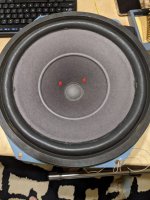
Anybody else here think this woofer was badly repaired a while ago?
I think that originally would have had a pleated paper accordion surround and from the size of the dust cap I suspect a VC about an inch in diameter
Late 1940's early 50's??
I think that originally would have had a pleated paper accordion surround and from the size of the dust cap I suspect a VC about an inch in diameter
Late 1940's early 50's??
Don't know whether the surround is original or not, but this 'woofer' would be better described as a 'mid/bass' driver.
The driver's central area has been engineered especially to reproduce the midrange/low treble frequencies.
This driver is designed to be connected directly to the amplifier terminals and to cover most of the audible range. The tweeter supplies only the missing top octave or so, i.e. the very highest frequencies, via its 4uF capacitor.
Speaker systems like this did not have complicated crossover circuits. The idea was to throw as much sound around as possible and not waste energy in the crossover components.
Don't know whether the surround is original or not, but this 'woofer' would be better described as a 'mid/bass' driver.
The driver's central area has been engineered especially to reproduce the midrange/low treble frequencies.
This driver is designed to be connected directly to the amplifier terminals and to cover most of the audible range. The tweeter supplies only the missing top octave or so, i.e. the very highest frequencies, via its 4uF capacitor.
Speaker systems like this did not have complicated crossover circuits. The idea was to throw as much sound around as possible and not waste energy in the crossover components.
Hey really appreciate the help. So would you agree with Moondog that the Vas is incorrect? Cause with that Vas figure I am getting a 80 to 100 litre closed box or I might go aperiodic. It seems my DAts V3 is calibrating with great difficulty so the readings could be wrong.
So probably not worth even attempting a simple crossover? Thats what I am presuming according to what you mentioned and it seems to be what the original speaker had.
Just to confirm and to double check the 4uf cap which Ill obviously change is in series before the tweeter can someone link me to an example of how the capacitor is connected and to what? If the woofer is connected directly to amplifier then where does the tweeter connect to?
The tweeter is a 4 ohm tweeter according to DATs V3.
It seems the capacitor is connected to the number 2 which must be the negative with a wire from number 1 connecting to the wire from number 2. Is this series?

I can say that enclosure volumes of that magnitude are typical for vintage bass drivers.So would you agree with Moondog that the Vas is incorrect? Cause with that Vas figure I am getting a 80 to 100 litre closed box
Sounds like the Vas should be more like 39 litres rather than 3.9 litres.
The drivers are wired as shown in the attachment (ignore the ohm values).
I would stick to this simple crossover in line with the original design intentions.
Really appreciate it. That is simple enough to accomplish.
I can say that enclosure volumes of that magnitude are typical for vintage bass drivers.
Sounds like the Vas should be more like 39 litres rather than 3.9 litres.
That is what I suspected with forums mentioning higher QTS with vintage drives and large volume cabinets. But it looks like I have to wait for a DATS V3 replacement and try again to make sure the parameters are correct. I can't seem to calibrate DATS V3...
The original litre of the enclosure was about 60 litres.
But I can potentially start a mock up cabinet and measure the frequency range and see if the frequency ranges meet.
- Home
- Loudspeakers
- Multi-Way
- Old Vintage Tweeter Driver can't get VAS