Please Update the list yourselves when you type:
1. Jogi = 2PCB
2. qusp= 2-3PCB
3. Bas Horneman = 2 PCB
4. hihopes = 2PCB
5. guglielmope = 2PCB
6. Ryssen = 2PCB
7. kstlfido = 6PCB
8.cygnus x1 = 8PCB
9. regal = 4PCB
10. le`flu = 4 PCB
11. vgeorge = 2 pcb
12.jameshillj = 2 pcb
13.dodo = 1 pcb (one)
14.normundss = 2-3 PCB
15. stoolpigeon 4 PCB
16. Nikon1975 = 2 PCB
17. pchw = 4 pcb
18. boudy = 2 PCB
19. Yunick = 1 PCB
20. JimS = 4PC
21. Cambe = 3 PCB
22. av-trouvaille = 6-8 pcb
23. Jean-Charles = 4 pcb
24. Ferrari = 4 PCB
25. piero7 = 2 pcb
26. Zekk needs ONE
27. Joshua_G = 1 PCB
28. ernesternest 2 PCB
29. wobii = 2 pcb
30. Jaap = 2 pcb
31. noizas = 3 pcb
32. housing = 2 pcb
33. h-wan = 1 pcb
34. ichiban = 2 pcb
35. Adamus = 1 pcb
36. mikel_ann = 2 pcb
37. flyboi = 2 pcb
38. ims = 1 pcb
39. touchdown = 1 PCB
edited to 1 pcb, i didnt realise 1pcb = two boards. thanks
Simpler Simplistic design by Salas
[on the 22-3 production was finished 2 – 4 - 2010
Then I will send the first day for all of you!
]
Not sure I understand the lead time, you're not saying it took 11 months to make the boards?
In this Tube (6n2 or 12AX), use some mA. you can use one suppy for it.
But i dont like SRPP for DAC, i fin in my house, if i still have PCb SRPP, i will gift you, don't pay money.
quanghao
If SRPP not good for DAC output can you suggest something better than SRPP and can use Simplistic Mosfet HV Shunt as PSU.
SRPP sounds awful in a DAC, it is very load dependant. Just use a low Rp high gain tube in bypassed cathode with output from the anode. Use 6n6p or 5842 (for more gain), sounds much better than a SRPP, trust me I've tried many tube DAC stages.
regal
What do you propose other than SRPP??
quanghao
Can I make Paypal transfer for 3 PCB in amount 3x30 USD, or I need to wait some options for postage cost?
Concerning gabanyayaya SRPP schematic - it shows like I/V ala Lampizator with 6N2P - one solution for I/V, amp and even buffer. If here is question of space in box, it is not worst solution, IMHO.
What is wrong with SRPP as I/V - can you share your experience?
gabanyayaya
Indeed you can use one shunt regulator as power suplly, but better substitute by it only diodes D1-D4 - leaving RC filters separate for L and R channels. This would be reasonable because even SRPP's upper tube works as CCS, this is true only if SRPP designed well - matched on specific Rload.
You can read about it here - The Tube CAD Journal,SRPP Decoded .
If you need to calculate SRPP, just please write me - s.navikas@zebra.lt, I will do it with TubeCAD for my pleasure.
So you saying SRPP only need a simple PSU like CRC filter....rather than the shunt...?
quanghao
regal
What do you propose other than SRPP??
You may have to use a different tube depending on gain required.
You may have to use a different tube depending on gain required.
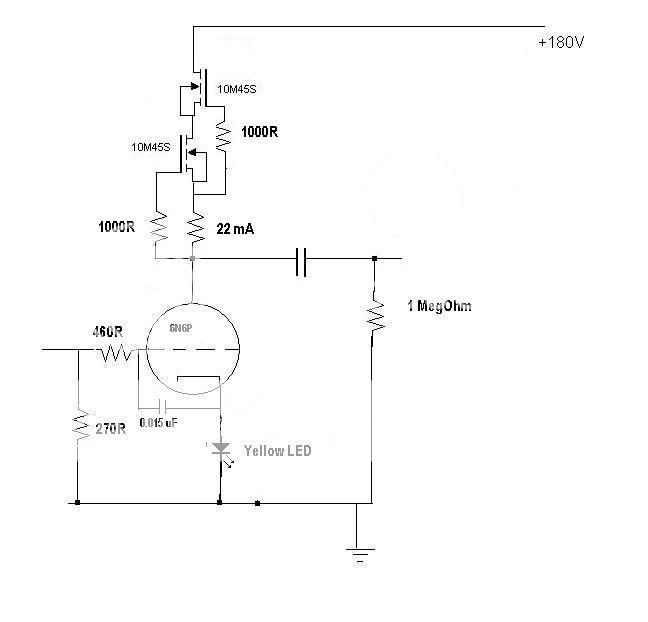
Why use LED ? What type?
Do you use a variable R next to 1000R ? So basically this + the shunt sound better than lampizapor ?
led bias is just another way of biasing the grid. the yellow LED will bias to 2v or so, just watch the current ratings, 22ma is quite hot for an LED.
leds have low dynamic resistance, so no need for electrolytic bypass caps as with resistors. less crap in the signal chain.
leds have low dynamic resistance, so no need for electrolytic bypass caps as with resistors. less crap in the signal chain.
So you saying SRPP only need a simple PSU like CRC filter....rather than the shunt...?
the sound is not good!
I always said that additional sources of energy affect 40% of sound quality. And I love power shunt.
the sound is not good!
I always said that additional sources of energy affect 40% of sound quality. And I love power shunt.
Do you use a variable R next to 1000R ? So basically this + the shunt sound better than lampizapor ?
Yes read Salas's 10m45s thread that explains how to set up a CCS. You can get LED's that handle 20+ mA's fine just look at the datasheets. You may want to use a 5842/6c45pi tube for higher gain so you can use a lower I/V resistor. You have to be able to calculate final output to set this up for a DAC and yes it sounds much better than an SRPP, its single ended without cathode output. If you google 6c45pi TDA1541 you will see that most of the orient has switched to this sort of stage rather than SRPP.
Yes read Salas's 10m45s thread that explains how to set up a CCS. You can get LED's that handle 20+ mA's fine just look at the datasheets. You may want to use a 5842/6c45pi tube for higher gain so you can use a lower I/V resistor. You have to be able to calculate final output to set this up for a DAC and yes it sounds much better than an SRPP, its single ended without cathode output. If you google 6c45pi TDA1541 you will see that most of the orient has switched to this sort of stage rather than SRPP.
Can you please post a link to Salas's 10m45s thread?
Please Update the list yourselves when you type:
1. Jogi = 2PCB
2. qusp= 2-3PCB
3. Bas Horneman = 2 PCB
4. hihopes = 2PCB
5. guglielmope = 2PCB
6. Ryssen = 2PCB
7. kstlfido = 6PCB
8.cygnus x1 = 8PCB
9. regal = 4PCB
10. le`flu = 4 PCB
11. vgeorge = 2 pcb
12.jameshillj = 2 pcb
13.dodo = 1 pcb (one)
14.normundss = 2-3 PCB
15. stoolpigeon 4 PCB
16. Nikon1975 = 2 PCB
17. pchw = 4 pcb
18. boudy = 2 PCB
19. Yunick = 1 PCB
20. JimS = 4PC
21. Cambe = 3 PCB
22. av-trouvaille = 6-8 pcb
23. Jean-Charles = 4 pcb
24. Ferrari = 4 PCB
25. piero7 = 2 pcb
26. Zekk needs ONE
27. Joshua_G = 1 PCB
28. ernesternest 2 PCB
29. wobii = 2 pcb
30. Jaap = 2 pcb
31. noizas = 3 pcb
32. housing = 2 pcb
33. h-wan = 1 pcb
34. ichiban = 2 pcb
35. Adamus = 1 pcb
36. mikel_ann = 2 pcb
37. flyboi = 2 pcb
38. ims = 1 pcb
39. touchdown = 1 PCB
40. grufti = 2 PCB
added 2 pcb. thanks
So you saying SRPP only need a simple PSU like CRC filter....rather than the shunt...?
No, I had idea that you can use one shunt regulator for both channels, separating power supply for L and R channels via CRC filters (like in your drawing).
Theoretically this is ok, as BALANCED SRPP uses constant current.
Balanced SRPP means, that output capacitor is loaded with load, for that was calculated - LOAD IS PART OF SRPP!
So if you are loading SRPP not exactly R you are designed for, you will have non A class here - distortion.
So two shunt regulators are exactly in place with SRPP, when those are NONbalanced 😉
Seriously would recommend you to use SE for I/V stage - plate follower or grounded cathode. Or even better mumetal transformer, but this is another story...
Simpler Simplistic design by Salas
A. Information about Salas shunt:
http://www.diyaudio.com/forums/powe...stic-mosfet-hv-shunt-regs-97.html#post2084348
Thank you Salas
_______________
B. Information PCB
+ One PCB:
2 x Simpler Simplistic
2 x Heater Power Supply+ Quality:
two layers , gold-plated, 1.6 mm thickness
C. The price includes:
PCB + Shipping (surface mail) + fee PayPal :
1. PCB = 30$
2. PCB = 55$
3. PCB = 85$
4. PCB = 110$
Hi everyone. Current everything I was ready to submit designs for manufacturers to make circuits.
So you have registered, please let me transfer the funds to my order soon.
Time to receive funding to start from today to 16-3-2010
When I receiving funding will be made immediately,
on the 22-3 production was finished 2 – 4 - 2010
Then I will send the first day for all of you!
Thank you and please transfer money to my account
My papal account: quanghao168@yahoo.com.vn
quanghao from 15$ each pcb as you wrote me in MP now the price is just double, don't you think it's a bit too much for surface mail?
$30 U.S. is dear, very dear for a PCB.
What's going on here?
30 USD for 2 x simpler simplistic + 2 x filament PSU regulator, totally 125mmx 250mm PCB, is not so expensive, IMHO.
Same size, but not gold plated bare regular PCB in ebay shops costs 15 - 22 USD even without delivery cost.
Here we have delivery and Paypal fee already included.
And this is not regular production of bare PCB...
Regards
Yes read Salas's 10m45s thread that explains how to set up a CCS. You can get LED's that handle 20+ mA's fine just look at the datasheets. You may want to use a 5842/6c45pi tube for higher gain so you can use a lower I/V resistor. You have to be able to calculate final output to set this up for a DAC and yes it sounds much better than an SRPP, its single ended without cathode output. If you google 6c45pi TDA1541 you will see that most of the orient has switched to this sort of stage rather than SRPP.
I like the circuit just now, simple to build but I have a V-out DAC...witht is work?
I like the circuit just now, simple to build but I have a V-out DAC...witht is work?
Schematic that you provided us is compatible with low signal I-out DAC as TDA1541, AD1865, etc (just different R I/V needed). It is simply too high gain for V out type DACs with 1 - 2V RMS ready.
For V-out DAC with opamp V output ready I would use cathode or anode follower, based on 6N6P or something like that valve. Schematic and calculation you can find in lampizator site, just google "lampizator 6N6P".
If supply voltage or tube type is not ok for you, let me know, I can help with calculations.
However take care - Vout as usual is worse approach, than I -out (except few TDA, AD and Wolfson DAC). And you will have one more capacitor in chain.
So the sound can be not so natural, IMHO.
- Status
- Not open for further replies.
- Home
- More Vendors...
- Quanghao Audio Design
- OLD THREAD Simplistic Mosfet HV Shunt (The Simpler Simplistic Design by Salas)