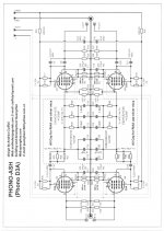
I read an article somewhere on the internet, with a phonoamp project with the D3a tube. Thought that the schematic was a little "messy", with three resistors on the schematic and only two of the mentioned on the drawing. Also found, probably, an old schematic of the same phonoamp, with fewer resistors and capacitors. Anybody outthere who built thisphonoamp?
Hi Stenak, I built that phono preamp a while ago when the thread was active.
I still have to compare it to another one. I am making the N@im phono stage atm. What would you like to know?
Attachments
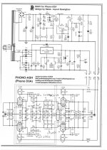
Hi. Thanks for answering! I found two different schematics on the internett, the one found early in this thread, and another one by Ciuffoli, maybe an earlier curcuit?, see link!. I think the schematic of the one Quanghao is a little bit "messy"? Three resistors and on the drawing marked 2 x 47K? Just ordred D3a tubes and I will use p2p soldering, not pcb. My question is: Is the schematic from the link Ok? Much easier to use if you are p2p soldering?
Hi-end phono preamplifier
Hi-end phono preamplifier
Hi. Thanks for answering! I found two different schematics on the internett, the one found early in this thread, and another one by Ciuffoli, maybe an earlier curcuit?, see link!. I think the schematic of the one Quanghao is a little bit "messy"? Three resistors and on the drawing marked 2 x 47K? Just ordred D3a tubes and I will use p2p soldering, not pcb. My question is: Is the schematic from the link Ok? Much easier to use if you are p2p soldering?
Hi-end phono preamplifier
Hi Stenak,
The circuit on the webpage you posted uses different setup and lately changed to use smaller mica capacitors.
I have done mine according to the latest design (see attachments).
Cheers
Attachments
Phono stage
Stenak,
The use of resistors in parallel and in opposite orientation it's Ciuffoli's style. Probably he's got radio engineering background where two identical resistor are connected in parallel with opposite orientation to cancel residual inductance. In audio it's a little overkill but that's his style.
Don't worry if you see three resistor in parallel on the schematic. I think those reflect the positions available on the PCB to give flexibility with paralleling different values. Just follow the text. If you see 2 x 47K it means 1 x 23.5K 2 x 47K or 3 x 15.6K parallel and so on, regardless the number of resistors on the schematic.
With regards to p2p vs PCB, I think for phono stage I would prefer PCB. With p2p you could pickup some noise. The PCB is easy to do. Just use Osmond PCB on MAC (I use Mac) and then upload the gerber files on Fusion PCB Manufacturing & Prototype PCB Assembly - Seeed Studio and you will have it in 1-2 weeks.
Let me know if you need more information.
Hi. Thanks for answering! I found two different schematics on the internett, the one found early in this thread, and another one by Ciuffoli, maybe an earlier curcuit?, see link!. I think the schematic of the one Quanghao is a little bit "messy"? Three resistors and on the drawing marked 2 x 47K? Just ordred D3a tubes and I will use p2p soldering, not pcb. My question is: Is the schematic from the link Ok? Much easier to use if you are p2p soldering?
Hi-end phono preamplifier
Stenak,
The use of resistors in parallel and in opposite orientation it's Ciuffoli's style. Probably he's got radio engineering background where two identical resistor are connected in parallel with opposite orientation to cancel residual inductance. In audio it's a little overkill but that's his style.
Don't worry if you see three resistor in parallel on the schematic. I think those reflect the positions available on the PCB to give flexibility with paralleling different values. Just follow the text. If you see 2 x 47K it means 1 x 23.5K 2 x 47K or 3 x 15.6K parallel and so on, regardless the number of resistors on the schematic.
With regards to p2p vs PCB, I think for phono stage I would prefer PCB. With p2p you could pickup some noise. The PCB is easy to do. Just use Osmond PCB on MAC (I use Mac) and then upload the gerber files on Fusion PCB Manufacturing & Prototype PCB Assembly - Seeed Studio and you will have it in 1-2 weeks.
Let me know if you need more information.
Last edited:
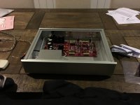
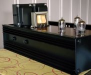
I made it for myself
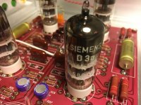
I got the boards from a friend many years ago. Now I decided to build the phono stage using L M Ericsson (Sweden) D3a tubes.
Two Hammond 369GX transformers are connected to give 12.6V for heating (two 6.3V in series) and two 230V windings in parallel to give enough current for high voltage.
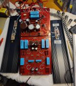
12.6V is much too much for the LM317. An MJE3055 is helping and both are mounted on a large heat sink. Two heat sinks make the side panels of the RIAA.
Very low ripple and noise. Heatsink stabilize at around 45C.
The high voltage regulator was not so easy to get working. Much too often the shunt regulator FET shorted. Ended up with a 1uF across it. Has worked fine since it was added.
The RIAA correction shows me that there is too much bass lift. +20dB already at 100Hz. Too much attenuation at 20kHz. Totally it gives a sound on the dark side.
I got the boards from a friend many years ago. Now I decided to build the phono stage using L M Ericsson (Sweden) D3a tubes.
Two Hammond 369GX transformers are connected to give 12.6V for heating (two 6.3V in series) and two 230V windings in parallel to give enough current for high voltage.
12.6V is much too much for the LM317. An MJE3055 is helping and both are mounted on a large heat sink. Two heat sinks make the side panels of the RIAA.
Very low ripple and noise. Heatsink stabilize at around 45C.
The high voltage regulator was not so easy to get working. Much too often the shunt regulator FET shorted. Ended up with a 1uF across it. Has worked fine since it was added.
The RIAA correction shows me that there is too much bass lift. +20dB already at 100Hz. Too much attenuation at 20kHz. Totally it gives a sound on the dark side.
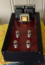
Pictures of my D3a phono
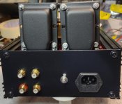
Side panels are heat sinks. The rest is aluminium sheet metal.
Side panels are heat sinks. The rest is aluminium sheet metal.
Attachments
When completed I found a gain difference of 2-3 dB between the channels.
After much testing and trying the channels got equal gain after removing the cathode bypass capacitors in the final stage. 270uF.
This reduces gain. Ended with 38dB which is acceptable.
After much testing and trying the channels got equal gain after removing the cathode bypass capacitors in the final stage. 270uF.
This reduces gain. Ended with 38dB which is acceptable.
When completed I found a gain difference of 2-3 dB between the channels.
After much testing and trying the channels got equal gain after removing the cathode bypass capacitors in the final stage. 270uF.
This reduces gain. Ended with 38dB which is acceptable.
Each tuba have a different voltage gain but 2-3dB are very high.
You can try to exchange one tube with one of the other channel to see if the difference is lower.
The cathode bypass capacitor cannot create differences on channels if the quality of this cap is good.
Now I suggest the UKZ 470uF 6.3V from Nichicon probably better previous OS-CON.
If you eliminate the bypass capacitor the output impedance of any stage increase and RIAA frequency response is no more correct.
Gain difference
Thank you for replying.
I have a "lot" of these tubes. Something else than the tube is causing this difference.
The signal levels at the grid/input are equal.
Anyway, thank you.
Thank you for replying.
I have a "lot" of these tubes. Something else than the tube is causing this difference.
The signal levels at the grid/input are equal.
Anyway, thank you.
it is well! thanksPictures of my D3a phono
Side panels are heat sinks. The rest is aluminium sheet metal.
D3a is not easy to find and now are expensive
A good idea should be use 6Z9P - 6ZH9P or 6Z51 but some changes are necessary in RIAA network.
I can try to simulate it.
A good idea should be use 6Z9P - 6ZH9P or 6Z51 but some changes are necessary in RIAA network.
I can try to simulate it.
Where did you get the chassis ? Do you have a link?Hi Stenak, I built that phono preamp a while ago when the thread was active.
I still have to compare it to another one. I am making the N@im phono stage atm. What would you like to know?
Was late on this preamp and missed on PCBs.Do you know if its available anywhere?
Hello, do you know where to get PCBs for this preamp based on D3a ?it is well! thanks
it is well, how you think about the sound? thanks
hello!D3a is not easy to find and now are expensive
A good idea should be use 6Z9P - 6ZH9P or 6Z51 but some changes are necessary in RIAA network.
I can try to simulate it.
6z51 can I substitute with ef184?
on the other hand i have 2 D3a tubes can I use in the fist stage D3a and in the second stage 6Z51?
- Home
- More Vendors...
- Quanghao Audio Design
- OLD THREAD Hi-end phono preamplifier by Andrea Ciuffoli