if you can bias it and set DC offset, opto is good
there must be some other reason for distortion
do you have a scope?
there must be some other reason for distortion
do you have a scope?
Have scope - yes
Have scope that I know how to use - maybe
I raised the bias from 1A to 1.4A hoping it would release more energy but no change. 2SA1943 from Digikey.
If I disconnect the front end, can I feed signal into the OP section at the JUMPER to bypass diamond buffer?
Same for R111 (0R) to bypass Cinemag?
Have scope that I know how to use - maybe
I raised the bias from 1A to 1.4A hoping it would release more energy but no change. 2SA1943 from Digikey.
If I disconnect the front end, can I feed signal into the OP section at the JUMPER to bypass diamond buffer?
Same for R111 (0R) to bypass Cinemag?
for silicone P channel, R122 needs to be 22R
for Ge, 10R
yes, if you disconnect jumper, you can feed signal there - after the buffer , DC level is 0V
same applies if you lift R111, after xformer, DC level is 0V
if you feed it with clean sine (say 100mV-200mV) before autoformer, normally expected is clean sine at output, 4 times in value
if you feed it with clean sine (say 1V) after autoformer, normally expected is clean sine at output, same value
Feeding it at the jumper (on X), 100mV input is putting out 380mV output and seems relatively clean but it is probably jumping very slightly. As I increase input the trace starts to jump and does this regularly although it's still clean sine wave. Jump makes it offset with same amplitude


now check buffer itself
feed at input, scope at open jumper
then scope at jumper closed
of course, you did set buffer to 20mA and 0 offset, having approx. half rail voltage at JFets........
feed at input, scope at open jumper
then scope at jumper closed
of course, you did set buffer to 20mA and 0 offset, having approx. half rail voltage at JFets........
Update - left channel (working one) goes from 0.2% to 0.4% and stays there up until about almost 30W and then climbs up to over 5%THD so I can live with that just for dating period as I haven't tried GE yet. Oddly FE and OS measure very nicely independently at below 0.1%THD each.
Back to right channel (side that doesn't bias). Vgs across M101 is 6.0xV. Vgs at IRFP240 is 3.0xV and 0.0xV across 2SK1943. over 500mV across R118 so current going through at least 1 side of LT3092. R117 is on bottom of board so I cannot measure it.
R122 is 22R for both boards and using 2SK1943.
News Flash! Live from the scene

Nobody wants to wait to the end for the surprise so picture first, glory second.
Vgs (Vbe) at 2SK1943 was the strange thing so I started checking value of R122 at other points and 22R checked out. Next R129 (0R), maybe it's broken? Tested OK. Check from Source pin of M101 to OUT+ and expect 22R but ... 500M??? Should be 22R so maybe check solder joints again, look at board for burned/broken trace perhaps? That's when I see the trace from R129 (0R jumper) going to closest pin on M101, not the far one that I expect. Taking a closer look, I see that M101 is mounted on the OTHER side of heatsink compared to other board. I have habit of preparing both boards at the same time so I prepared IRF9510 on the same side of heatsink and installed ... that was my mistake - M101 was in backwards.
As you can see, problem fixed, this channel has less THD than the other one by about 0.1% above 2W and easily over 30W below 1%THD. +H2 as you can see from the giggly wiggly and confirmed with negative phase angle number in REW.
How does it sound? I don't know yet. I need to put into test mule but I am tempted to just go ahead with GE because I have enough silly cone amps already ...
Thank you ZM!
to be continued ...
Back to right channel (side that doesn't bias). Vgs across M101 is 6.0xV. Vgs at IRFP240 is 3.0xV and 0.0xV across 2SK1943. over 500mV across R118 so current going through at least 1 side of LT3092. R117 is on bottom of board so I cannot measure it.
R122 is 22R for both boards and using 2SK1943.
News Flash! Live from the scene
Nobody wants to wait to the end for the surprise so picture first, glory second.
Vgs (Vbe) at 2SK1943 was the strange thing so I started checking value of R122 at other points and 22R checked out. Next R129 (0R), maybe it's broken? Tested OK. Check from Source pin of M101 to OUT+ and expect 22R but ... 500M??? Should be 22R so maybe check solder joints again, look at board for burned/broken trace perhaps? That's when I see the trace from R129 (0R jumper) going to closest pin on M101, not the far one that I expect. Taking a closer look, I see that M101 is mounted on the OTHER side of heatsink compared to other board. I have habit of preparing both boards at the same time so I prepared IRF9510 on the same side of heatsink and installed ... that was my mistake - M101 was in backwards.
As you can see, problem fixed, this channel has less THD than the other one by about 0.1% above 2W and easily over 30W below 1%THD. +H2 as you can see from the giggly wiggly and confirmed with negative phase angle number in REW.
How does it sound? I don't know yet. I need to put into test mule but I am tempted to just go ahead with GE because I have enough silly cone amps already ...
Thank you ZM!
to be continued ...
whoopsa!
it is expected that - if you use matched pair of IRFP240 and matched pair of Pchannel (be it Ge or Si) that THD figure between channels is close
but, believe me - in this case pretty much irrelevant, inherent Wakooness of amp dominating over those minor differences
it is expected that - if you use matched pair of IRFP240 and matched pair of Pchannel (be it Ge or Si) that THD figure between channels is close
but, believe me - in this case pretty much irrelevant, inherent Wakooness of amp dominating over those minor differences
'twas damn close to andy&pepenino damngreenhorn level ....... looking at damn heatsink overlay, not on what's primary important - metal tab of TO220
but chill, whatever mistake you make 'till the end of life....... be sure than ZM made it already, at least twice and that was just mild one, in ZM's list

but chill, whatever mistake you make 'till the end of life....... be sure than ZM made it already, at least twice and that was just mild one, in ZM's list
I will swap out IRFP240 for matched pair when I figure out how to mount Ge devices. How hot do these old guys get?
Guilty as charged

Guilty as charged
not too hot, if you bias it as prescribed
with Si in output, you can bias it as regular Papamp (up to 40-45W per device), but taking care of Ge, no more than 1A of Iq ...... that being approx 20-22W per device
hope pics in first posts can help with details ...... you'll need decent L bracket (40x40x5mm), at least 100mm long
had some listening yet?
Twitchie! Excellent work that you solved the problem... because M101 was my problem too!
Mounts on the other side of the heat sink as the other channel board!
Doh!
I don't know how many times I checked all the parts but missed checking M101 orientation.
So now everything works!
Congrats ZenMod! Another fantastic AMP! I've been playing it all afternoon and it
sounds exceptionally good!
Some quick Photos...
Bruce
Attachments
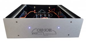
Excellent work Bruce and I'm glad to hear that you have yours working now. I am jealous of your faceplate and I happen to have a few of these 3U/400 coming my way with silver faceplate just like yours. This is my favorite chassis to use and has plenty of space to keep power transformers further away from cinemags (better than the 300mm in this respect) while being large enough to keep temperatures sane for most amps. SissySIT (R1) is probably the only one I wouldn't put in a 3U/400. Great looking amp! Congratulations and please share your listening impressions.
Cheers,
Stephen
I am jealous of your faceplate and I happen to have a few of these 3U/400 coming my way with silver faceplate just like yours. This is my favorite chassis to use and has plenty of space to keep power transformers further away from cinemags (better than the 300mm in this respect) while being large enough to keep temperatures sane for most amps. SissySIT (R1) is probably the only one I wouldn't put in a 3U/400. Great looking amp! Congratulations and please share your listening impressions.Cheers,
Stephen
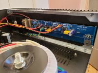
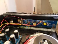
Wow that looks great Bruce! I really like the logo. Is that small heatsink sufficient for the Ge or does it transfer heat to the larger modu heatsink in some way?
Very tidy build👌
Very tidy build👌
Twitchie! Excellent work that you solved the problem... because M101 was my problem too!
Mounts on the other side of the heat sink as the other channel board!
Doh!
I don't know how many times I checked all the parts but missed checking M101 orientation.
So now everything works!
Congrats ZenMod! Another fantastic AMP! I've been playing it all afternoon and it
sounds exceptionally good!
Some quick Photos...
Bruce
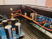
Bruce - I can't see did you made contact between small and main heatsink..... and I hope you did
there is approx 20W of heat in each output part, so small hsink is not enough alone
care to show detailed ?
I would put some thermal grease between the two adjacent heatsinks and also between the heatsink and the frontplate,
so it becomes one big heatsink.
so it becomes one big heatsink.
Oh MightyZMBruce - I can't see did you made contact between small and main heatsink..... and I hope you did
there is approx 20W of heat in each output part, so small hsink is not enough alone
care to show detailed ?
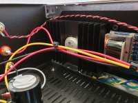
Reading this and another concerning the bracket (5x40x40, >=100 mm) I am worried (as usual) about the size I used, 40x40x4, barely bigger than the germanium-bug…
Should I learn to stop worrying and love the heat, or replace them right away?
( image here:
you're good
on the verge, but still good - if you did apply thermal grease between L and main heatsink
on the verge, but still good - if you did apply thermal grease between L and main heatsink
- Home
- Amplifiers
- Pass Labs
- Old Soul