Yes, I saw it. (And thanks for posting the excerpt, I forgot it)
Jan is a good man 🙂
As mr Borbely.
And ZM.
…
Jan is a good man 🙂
As mr Borbely.
And ZM.
…
Did mount 1T813 today, in place of 2N1099
fired it up, it set itself exactly at same Iq (as previously 2N1099) , did just minor tweak of output offset
same situation for both channels - everything perfect in static state
then connected old crummy Sigene to input, scope to out, no load, just to check does modulation reaching output
first channel OK
second channel - started , and somewhere at half ( of max) thingie just went South - speaker DC protection dissengaged relays, got 48V across 0R11 resistor group ( where I need to see 110mV)
powered it off, logical check - dead mosfet, dead Ge, two 0R22 resistors dead ( there is a reason why there are 2 or 3W jobbies)
was it 1T813 Dud ? most likely ...... and now I'm thinking what and how to test them if I decide to get them in quantity
it seems test with actual load, fastest way of Ge tossed in 1L container of demi water is easiest way to do it
anyway - replaced what's Dodo, checked rest of circuit and fired it up again
this time everything went good, so did tried both channels with load, up to clipping
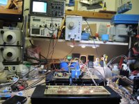
ZM, Please don't get angry at me, but if I look at your Pictures, and the Table, then I feel real at HOME> I know only one Working table that can compare on the negative Side to yours... And that's MINE..
Please, it's just only that most here have a neat and clean table - clean in the meaning of almost empty Table. My Table could be the big brother of yours..
But, were someone is working there traces are to be found..
So, forgive me, but I had a big laughter when I looked at your pics.. Felt at home.. and that's a compliment..
Enjoy Weekend.. Will place one of my table later that evening as it is today , Just that you see what I mean..
Respect & Regards
Chris
@ZM
Just to keep my word..
Here the some part of my working table.. too crowded..
That's about the half to the left side..
but the most important thing is, these devices which are created on top of these tables..
Enjoy weekend
Regards
Chris
Just to keep my word..
Here the some part of my working table.. too crowded..
That's about the half to the left side..
but the most important thing is, these devices which are created on top of these tables..
Enjoy weekend
Regards
Chris
Attachments
Last edited:
do not worry
Papa's bench is the same, except when he's showing off in some on-line event
he probably needs 2 days just to remove clutter visible on cam
Papa's bench is the same, except when he's showing off in some on-line event
he probably needs 2 days just to remove clutter visible on cam
Happy New Year Greedies and Dodoesses! I am happy to announce that a wedding is coming up but we don't know who's getting married yet. Technically I haven't seen anyone show a complete and/or running Old Soul aside from Wakoo Master's test bed version so I will assume that the title for 'First' is still unclaimed yet. 🏎️🐎🏇🥇
Today's lovely bride is wearing Cinemag CMOQ-4HPC high nickel attire for the special occasion

The first bachelor is from Germania

The second bachelor is also from Germania

The third bachelor is from Japan

Stay tuned to find out how the first date goes

And then we'll see how the next dates go before we hear who gets selected for a life of happiness and beautiful music together ...

Today's lovely bride is wearing Cinemag CMOQ-4HPC high nickel attire for the special occasion
The first bachelor is from Germania
The second bachelor is also from Germania
The third bachelor is from Japan
Stay tuned to find out how the first date goes
And then we'll see how the next dates go before we hear who gets selected for a life of happiness and beautiful music together ...

https://www.diyaudio.com/community/threads/old-soul.370744/page-15#post-6850818
Myleftear, did you stop to chat with the pretty people and forgot to cross the finish line? How about some pictures and listening impressions of your Old Soul. You know the rules, no popcorn, no glory ... something like that 😉
Myleftear, did you stop to chat with the pretty people and forgot to cross the finish line? How about some pictures and listening impressions of your Old Soul. You know the rules, no popcorn, no glory ... something like that 😉
Aah, you got me!https://www.diyaudio.com/community/threads/old-soul.370744/page-15#post-6850818
Myleftear, did you stop to chat with the pretty people and forgot to cross the finish line? How about some pictures and listening impressions of your Old Soul. You know the rules, no popcorn, no glory ... something like that 😉
I unfortunately had to stop @ the biasing-ceremony and go out to hunt down some parts. Being seriously affected by undecidedness (concerning layout/parts arrangement), I didn’t dare to touch the unfinished thing since then—I would rearrange the PSU a third time, and probably will. Same for the germaniums, they’re placed so fhat the wires have to twist, which isn’t as elegant as it should be, so I will have to redo this part too.
i‘ll call it a long-range-popcorn-trajectory 😀
@twitchie: Looking good! I completely forgot about the Toshibas when I last ordered parts. But I suspect I will stick to the germanium.
Do you guys think it's feasible to wire both the mosfet and the Ge part 'off pcb'? This may give a bit more flexibility in the placement of the output devices on the heatsink. It this is ok, is there anything to watch out for (aside from, say, putting the gate resistor on the mosfet when mouting it offboard)?
Thanks,
Dennis
I'm close.
I have a left channel built from Zenmod's kit that biased properly and
passes audio.
On the right channel, since I had some smoke from wrong parts, I changed out all the pcb semi's with
Digikey parts. But on that channel I can't get any bias current. Swapped the 2N1099's and IRFP240's
between channels but those weren't the problem.
It's difficult to troubleshoot even with a good channel to compare with since voltages will change
as bias and offset are adjusted. I'm suspicious the Digikey optos might have the wrong sensitivity for
the circut but can't be sure. I tried PC817B C and D optos but no luck.
I've put in an order from the Mighty Zenmod for another kit with just one channel and for the next step I'll go ahead
and rebuild that channel with his parts.
Bruce
Dennis@twitchie: Looking good! I completely forgot about the Toshibas when I last ordered parts. But I suspect I will stick to the germanium.
Do you guys think it's feasible to wire both the mosfet and the Ge part 'off pcb'? This may give a bit more flexibility in the placement of the output devices on the heatsink. It this is ok, is there anything to watch out for (aside from, say, putting the gate resistor on the mosfet when mouting it offboard)?
Thanks,
Dennis
I put solder pins at R122/R22 on the underside of the board so I could change those resistors between 22ohms and 10 ohms depending on whether Big Si or Ge is being used.
Best
Bob
Dennis
I put solder pins at R122/R22 on the underside of the board so I could change those resistors between 22ohms and 10 ohms depending on whether Big Si or Ge is being used.
Best
Bob
@Dennis, I can help with the 2SA1943 when I see you next.
Some tips & tricks since there isn't a tips & tricks thread.
I raised R106/206 a bit so that I could get hooks on it for adjusting the front end but on the R channel board, this causes it to stick up. My TO-220 heatsinks are a bit tall so they bump into R106 so it's fortunate that the legs on the BD139/140 are so long. Not optimal but not going to lose sleep over it.
As far as mounting off board - the hole spacing follows UMS but you'll have to find some spacers or use sacrificial mosfets to use as spacers to mount the boards.
A tip for adjusting P104/204 - you can clip to either leg of R114 and the other probe can go to the shiny series of tiny holes on the board as that connects to pin 2 of IC101 or the other side of P104 and simply adjust in the appropriate direction to get it to minimum.
Pin headers for R122 are a good idea and I put those in as well but just know that you will be very close to M101/201 (IRF9510) heatsink. I put a layer of kapton tape on the back of the heatsink since I didn't put an insulator on the back of my 9510 and even if you do, be careful as the fastener will be touching the front unless you are using non-conductive fasteners as well.
First date was a disaster - connected everything on R channel and attempted to follow power up procedure for adjustment but just ended up with 16V on the output and shut everything down. Came back a few hours later and hooked up the L channel and similar results ... except this time I waited and waited and waited and waited probably more than 5 minutes and magically bias started to move. The entire time, offset was moving steady and I stayed patient because as MZM stated, a few volts at this point is not out of the question. I will go back and retry R channel but first we need to see how our date with 2SA1943 is going:


H3 is -20dB down from H2 so very happy about that. Phase is -53 degrees so somewhat positive H2. It is just a first date so let's see how the Germaniums handle it. Stay tuned!

H3 is -20dB down from H2 so very happy about that. Phase is -53 degrees so somewhat positive H2. It is just a first date so let's see how the Germaniums handle it. Stay tuned!
Ok, not my imagination. R channel doesn't want to play. I wait long enough and about 10 turns into the bias, after 20 minutes I get 19.8V on the output (offset) but no bias current flowing. Any suggestions on where to start troubleshooting? 💩😪😿
well, besides soldering (proper contacts where needed and no contacts where not needed)........
voltage between upper and lower mosfet...... is there any?
is there any current through LT3092, shown as voltage across R117/118
proper P channel mosfet in negative rail side?
adequate value of source resistor there - 10R for Ge, 22R for Si
that's for now ......
voltage between upper and lower mosfet...... is there any?
is there any current through LT3092, shown as voltage across R117/118
proper P channel mosfet in negative rail side?
adequate value of source resistor there - 10R for Ge, 22R for Si
that's for now ......
Ge got me more, but I can't be sure was it really better or that was purely because of greater wakoo factor
Interesting, Il Penitente was even more surprising - I did expect something funny from Ge mated with mosfet, but full bipolar OS ( Il Penitente) is showing even more uniform SET looking THD Spectra
go figure ........
Interesting, Il Penitente was even more surprising - I did expect something funny from Ge mated with mosfet, but full bipolar OS ( Il Penitente) is showing even more uniform SET looking THD Spectra
go figure ........
- Home
- Amplifiers
- Pass Labs
- Old Soul