Dear LV,
My first attempt at PCB design.
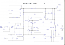
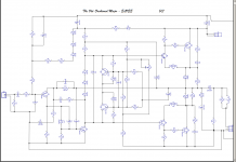
Please check Sch ver 5 also as some minor changes may be there.
Please remove .asc extn to open Dip-trace files.
--gannaji
My first attempt at PCB design.
Please check Sch ver 5 also as some minor changes may be there.
Please remove .asc extn to open Dip-trace files.
--gannaji
Attachments
Each rail needs decoupling (100nf and 220uf) or glitches off the mains can push transistors into breakdown region.
I always connect zero volts to a ground plane.
Leaving copper on costs nothing and helps with ground loops.
I always connect zero volts to a ground plane.
Leaving copper on costs nothing and helps with ground loops.
Where to begin...Dear LV,
My first attempt at PCB design.
Please check Sch ver 5 also as some minor changes may be there.
Please remove .asc extn to open Dip-trace files.
--gannaji
Let's try anyway:
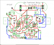
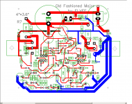
C17 should connect directly between the emitters of the power transistors, meaning it should be moved towards a more central position.
On its power side should arrive the supply connections and the GND of the speaker output.
On its amplifier side, the GND should connect to the input circuitry (J3) and the negative side of C1.
Its + side is relatively unimportant and can connect to the rest using the easiest path.
As said earlier, all the tracks carrying current (E & C of outputs, output, output GND, C17) should be made as wide as the space allows for.
In addition, the input GND track (with C1 C8 C4) should also be thicker.
R10 should connect directly to the + pad of C18.
By moving and rearranging some components and tracks, it should be relatively easy to arrive at a single-sided design (with maybe the odd strap, be I do not even think it is necessary)
Attachments
Where to begin...
Let's try anyway:
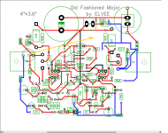
C17 should connect directly between the emitters of the power transistors, meaning it should be moved towards a more central position.Done
On its power side should arrive the supply connections and the GND of the speaker output.
Done
On its amplifier side, the GND should connect to the input circuitry (J3) and the negative side of C1.
Done
Its + side is relatively unimportant and can connect to the rest using the easiest path.
Done
As said earlier, all the tracks carrying current (E & C of outputs, output, output GND, C17) should be made as wide as the space allows for.
Done. Can be done more by experts.
In addition, the input GND track (with C1 C8 C4) should also be thicker.
Done. Can be done more by experts.
R10 should connect directly to the + pad of C18.
Done
By moving and rearranging some components and tracks, it should be relatively easy to arrive at a single-sided design (with maybe the odd strap, be I do not even think it is necessary)
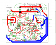
This the best I could achieve. Hope this should be passable.
--gannaji
Attachments

Last edited:
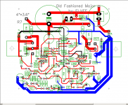
There are only three wires on top shown in black. Can be reduced to two.
The other colors are for clarity only.
The other colors are for clarity only.
Dear LV,
Did the modifications I can do. My knowledge ends here with the program. All this I did in the last 15 days by trial and error. Now hands up.
--gannaji
Did the modifications I can do. My knowledge ends here with the program. All this I did in the last 15 days by trial and error. Now hands up.
--gannaji
Attachments
Okay, thanks.
Building mine PTP on 3.5"x3.5" Nema CE boards, with TO-247 O.T.'s on the back parallel mounted on two each 3.5" x 1.5" x .75" 6 fin heat sinks. Heat sink screwed on bottom to board, OT legs through holes. Have a 80 mm fan blowing down both sinks side to side. Heat sinks salvaged from Samsung 52" LED TV.
Layout post 52 requires a 9" long heat sink for stereo, or about $50 I estimate if bought from farnell. Or four of the above sinks, with a chassis about 10" wide and 8" tall, which I do not have. Plus three 80mm fans instead of one, or one 5 1/2" fan $$.
Last edited:
Not quite rejected. AKA not rejected.It also belongs to the series I proposed to Daniel, but it was rejected at an early stage, probably because of its messy look.
I thought that the B+ topology was novel, exceptional, unusual, and wasn't quite like a class aB amplifier.
I had not mentioned it, but I had in mind some accessories, tone bank, active crossover, fun power filters, partial current drive, etc... which are easily compatible with a more typical class aB amplifier.
Sorry that I had not mentioned the integrated amplifier expansion path in a timely way.
- Home
- Amplifiers
- Solid State
- Old-fashioned amplifiers with a new twist (2)